18
www.tescom-ups.gr
USER MANUAL
DS 300H Series � 3/3 � 30 kVA � UPS CONTROLLED UPS
III. FRONT PANEL
3.1 Input
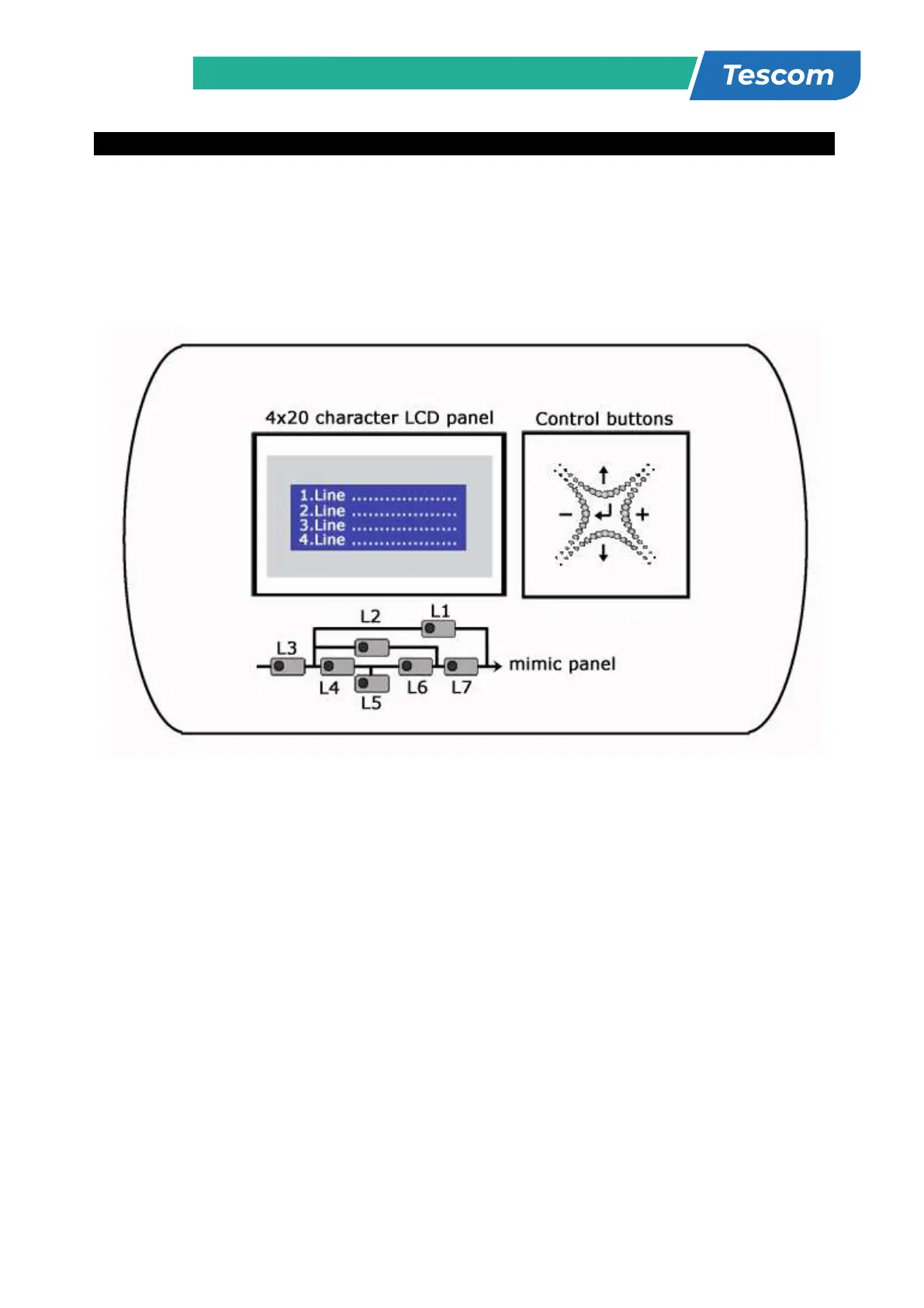
The front panel of UPS, consisting of a 4 lines alphanumeric display, 7 status lamps, plus 5
function keys, allows the complete monitoring of the UPS status. The mimic flow diagram helps to
comprehend the operating status of the UPS. By using the function keys operator can moves on
menus and change some parameters.
Figure 3.1 Control panel oft he UPS
L1
:
Maintenance bypass switch on indicator lamp
L2
:
Load on bypass indicator lamp
L3
:
Input voltage indicator lamp
L4
:
Rectifier run pilot lamp
L5
:
Battery operation indicator lamp
L6
:
Load on UPS indicator lamp
L7
:
Output switch on indicator lamp
There are 5 control buttons on the UPS Front panel ,ENTER button provides selection decleration,up and
down buttons provides to surf on menus, (+) and (-) buttons are used for adjustments or option selection.
3.2 Front Panel Menu Descriptions :
By using (↑), (↓) and ENTER buttons you can access the following menus. At the end of each menu there
is <ENTER> EXIT message will be showed, if you press enter you will exit to upper menu. All menus have
3 or 4 levels.
STATUS
→ Enter Status menu
MEASUREMENTS
→ Enter Measurements menu
ALARM LOGS
→ Enter Alarm logs menu
INFORMATION
→ Enter Information menu
OPTIONS
→ Enter Options menu
COMMAND
→ Enter Command menu
SERVİCE
→ Enter Service menu
PASSWORD
→ Enter Password screen
ADJUST
→ Enter Adjust menu
STATUS Status of the UPS
MEASUREMENTS INPUT Input measurements
BYPASS Bypass measurements
INVERTER Inverter measurements
OUTPUT Output measurements
DC DC measurements
GENERAL General measurements
ENTER - EXIT
ALARM LOGS
UPS LOG RECORD Page1
ENTER CLEAR LOG Page1
ENTER - EXIT
INFORMATION RS232 Comm 1:-- 2:-- Page1
Maximum UPS power Page1
Nominal voltage and frequency Page1
Inverter firmware version Page2
PFC firmware version Page2
Panel firmware version Page2
UPS Model Page3
Communication protocol Page3
Chassis nr Page3
ENTER - EXIT
OPTIONS LCD OPTIONS LCD panel options
COMM.OPTIONS Communication options
ALARM OPTIONS Alarm options
BYPASS OPTIONS Bypass options
ENTER - EXIT
COMMAND By-pass transfer Page1
Boost charge start Page1
Short battery test start Page1
Relay check Page2
Dialup modem programming Page2
Alarm sound ON/OFF Page3
Warning sound interval Page3
ENTER - EXIT
TIME Current time Page1
Current date Page1
Set hour Page2
Set minute Page2
Set day Page3