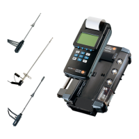
5. Setting up Control Unit and analyser box measurement system
33
5.5 Assigning function keys
5.5.1 Function bar
·
Measurement menu is activated.
As required:
Use or to change display view so that the function button which is to be
assigned is visible.
1
Press , release and immediately press the function button to be assigned:
-
A selection list of the possible functions appears.
2
Select function and confirm with .
Reversing the assignment:
1
Press menu key , release menu key and then immediately press the defined
function key.
2
Select empty field with and confirm with .
Function bar Control Unit analyser box
Free, non-assigned function button X
Zoom readings XX
Hold current reading X
Display max. values, since switch-on X
Display min. values, since switch-on X
Mean calculation X
Activate volume flow meas. (with a velocity or external X
differential pressure probe or internal pressure probe)
Activate/deactivate velocity measurement (with an external differential X
pressure probe or the internal pressure probe)
Measurement range 40 hPa for internal pressure sensor X
Measurement range 200 hPa for internal pressure sensor X
Zero pressure probe at user-defined probe socket (at least one X
differential pressure probe)
Zero the CO probe X
Start/stop measurement program X X
Determine system configuration X
Save readings XX
Print readings XX
Printer line feed XX
Turbulence calculation (with connected turbulence probe) X
Starts the measuring gas pump and indicates the readings on the display. When X
the function key P Start is clicked on, the function key changes to P Stop
The measuring gas pump stops, the readings are frozen at Hold X
Switches on and zeros velocity rate measurement with Pitot tube and pressure probe X
Manual storing of the current values under the displayed location names. X
Use of the two temperature inputs of the analyser box as separate X
2-channel temperature measurement with differential temperature display.
Activates the separate differential pressure measurement in the analyser box X
(draught measurement).The pump is stopped automatically once “d P” is activated.
Initiates the purging and zeroing phase (1 minute). The device draws fresh air X
through the measurement gas inlet or the fresh air valve (if fitted).
Manual change from measured gas to atmospheric air X
Manual deactivation of an activated CO sensor X
and purging with fresh air.
Manual activation of a deactivated CO sensor X
in the gas path.
Switching the dilution stage (digit in front of x corresponds to the set X
dilution factor)
Switching the HC module on/off X
X
Direct display of all error messages X
V OOn
Save
Delta TT
d PP
Null
COoff
COein
Gas ((air)
1 xx
HC OON
HC OOFF
DIAG
Max
Min
Mean
Vol
m/s
dP2
Pext=0
ppm=0
Start
Stop
Search
Save
Print
LF DDr
dP1
Turb
Zoom
Hold
P SStart
P SStop