4-Bit
DAC
To ADC
LOFF_STATP
LOFF_STATN
COMP_TH[2:0]
V
INP
V
INN
PGA
www.ti.com
Using the ADS1298ECG-FE Software
15
SBAU171D–May 2010–Revised January 2016
Submit Documentation Feedback
Copyright © 2010–2016, Texas Instruments Incorporated
ADS1298ECG-FE/ADS1198ECG-FE
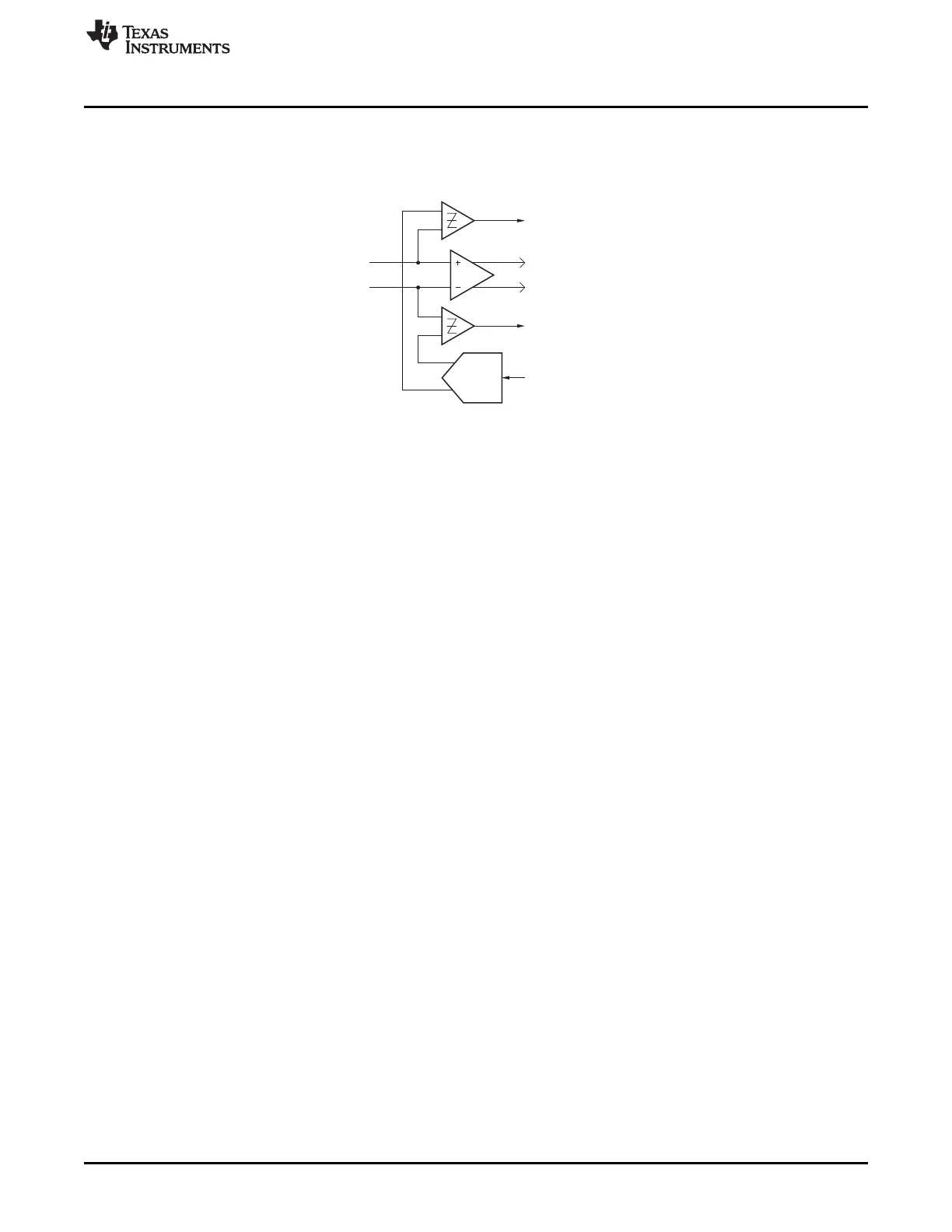
Figure 10 describes the mode for Lead-Off Detection (that is, resistive or current source) and the 4-bit
DAC settings to configure the lead-off threshold. Figure 13 illustrates the connections from the positive
and negative inputs to the lead-off comparators. The output of the comparators is viewed by using
Show/Poll Lead Off Status control as described in Section 3.2
Figure 13. LOFF_STATP and LOFF_STATN Comparators
3.4.3.2 Right Leg Drive Derivation Control Registers
The Right Leg Drive Derivation Control Registers enable the user to set any combination of positive and/or
negative electrodes to derive the RLD voltage that is fed to the internal right leg drive amplifier.