www.ti.com
ADS1x98ECG-FE Input Signals
29
SBAU171D–May 2010–Revised January 2016
Submit Documentation Feedback
Copyright © 2010–2016, Texas Instruments Incorporated
ADS1298ECG-FE/ADS1198ECG-FE
4 ADS1x98ECG-FE Input Signals
NOTE: Before evaluating specific ECG functions, it is recommended that the user acquire data with
inputs shorted internally. This configuration ensures that the board is operating properly.
4.1 Input Short Testing
By default, the EVM powers up with the individual channels to an internal short with a data rate of 500SPS
and a PGA gain of 6. Once the Acquire button is pressed, the Scope Analysis should reflect input-
referred V
PP
values less than 5µV
PP
4.2 Internal Test Signals Input
Configuration Register 2 controls the signal amplitude and frequency of an internally-generated square
wave test signal. The primary purpose of this test signal is to verify the functionality of the front-end MUX,
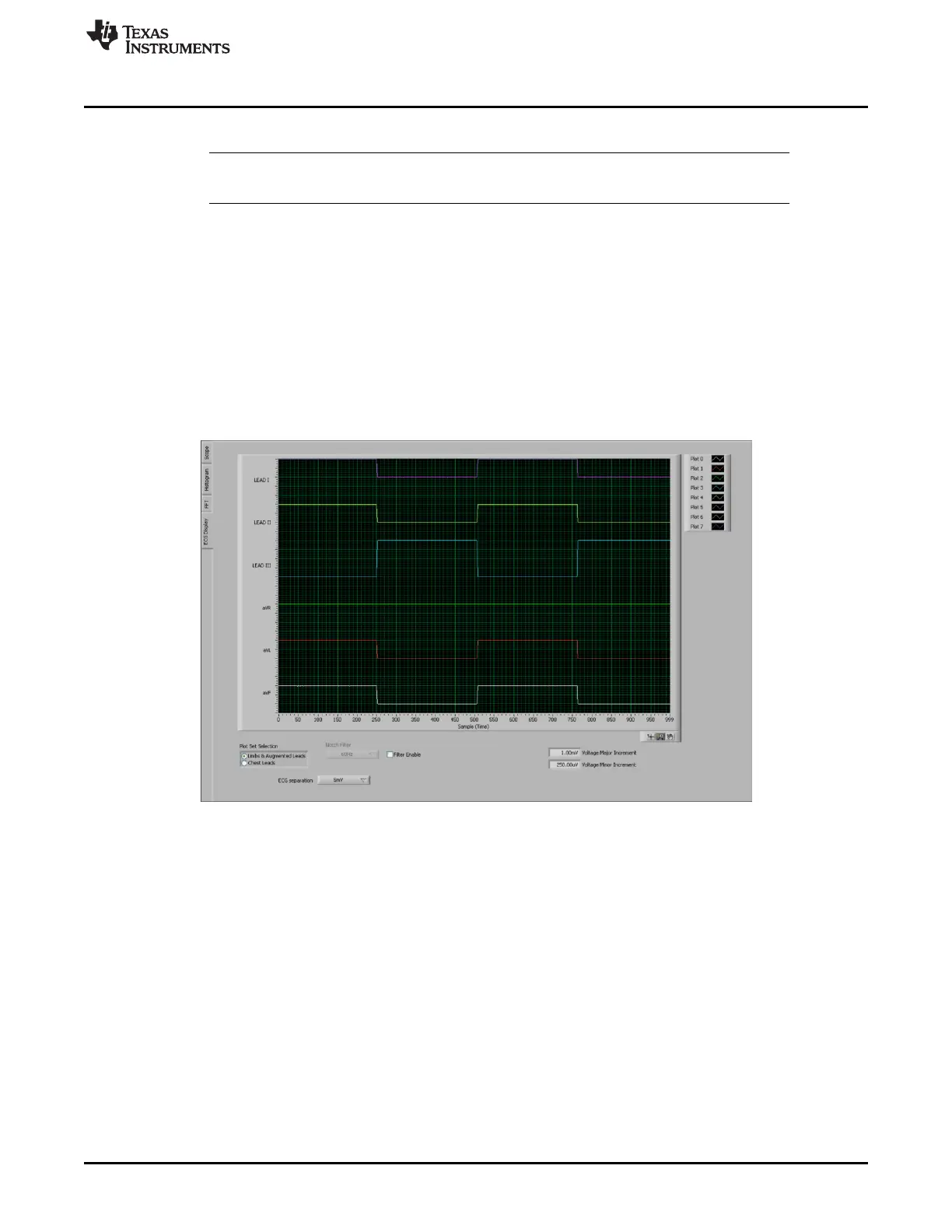
the PGA, and the ADC. The test signals may be viewed on the ECG Display tab, as Figure 31 shows.
Detailed instructions for using the ECG Display tab are provided in Section 3.5.4.
Figure 31. Example of Internal Test Signals Viewed on the ECG Display Tab