When calibrating the EVM voltage, remember the EVM uses 1% values for the cell simulator resistors.
Measuring each cell voltage value is recommended rather than using a common value if individual cell voltage
calibration is desired.
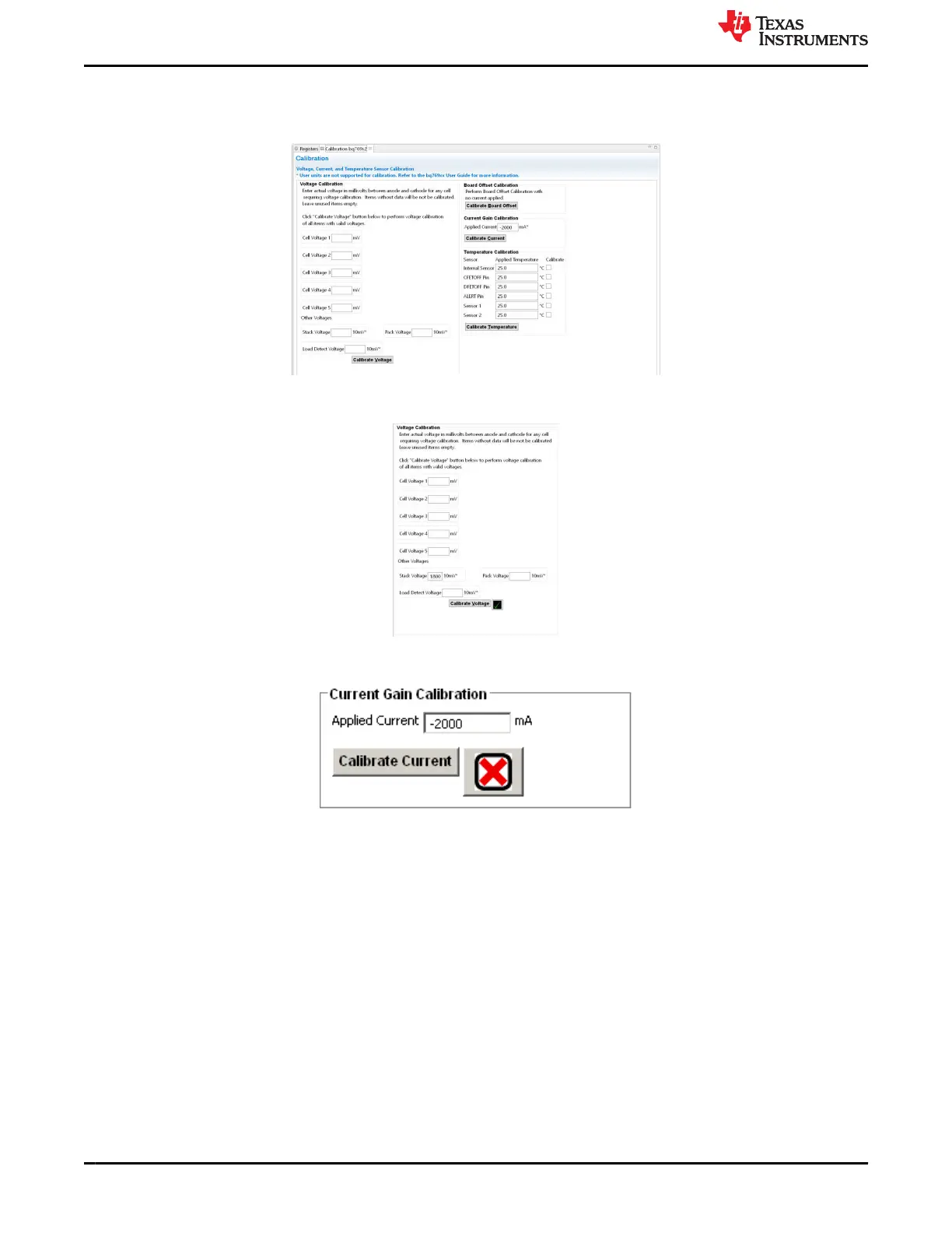
Figure 4-8. Calibration View
Figure 4-9. Example Voltage Calibration Success
Figure 4-10. Example Current Calibration Failure
4.8 Command Sequences
Features are controlled by commands as described in the BQ76922 technical reference manual (SLUUCG7).
Data is available from registers, and the registers view shows data, but a user may want to send specific
commands to the device. The Command sequences tool allows this operation and is shown in Figure 4-11.
The Device Send and Receive section allows read or write to a single or consecutive locations. The Command
Sequence section allows reads and writes to be intermixed in a sequence. Sequences may be stored to files or
called from files. Files may be assigned to buttons in the Command Sequence File Assignment Buttons section.
Results can be viewed in the Transaction Log and saved to a file if desired.
Battery Management Studio Software www.ti.com
12 BQ76922EVM Evaluation Module SLVU957A – SEPTEMBER 2019 – REVISED NOVEMBER 2021
Submit Document Feedback
Copyright © 2021 Texas Instruments Incorporated