3. Be sure the cell simulator shunts are removed
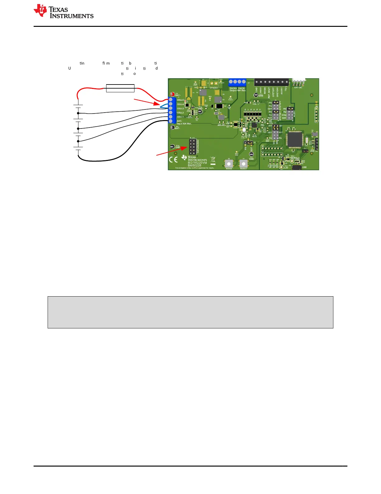
Figure 5-5 shows an example connecting cells with an EVM configuration reduced to 4 cells. Be sure the Vcell
mode is configured for the cells used. In this example 0x0017.
Remove cell
simulator shunts
to avoid draining
cells
If connec
ng cells con
rm opera
on before connec
ng.
Use all appropriate fusing, insula
on, isola
on and
shielding necessary for safe opera
on. Board has exposed
contacts. Do not leave unaended
For 4 cells, connect 3
rd
cell to both CELL3 and
CELL4 inputs
Figure 5-5. Example Connection with 4 Cells
5.7 Connecting to a Host
After initial operation of the monitor with the BQStudio software, it may be desirable to operate the board
connected to and controlled by a microcontroller board. J5 could be used to connect I2C signals to the
microcontroller board with GND and REG1 for a power supply from J2. The user should note that the J2 GND is
connected to the BQ76922 VSS and BAT- while the J5 reference is PACK-. With the connection shown in Figure
5-6 the MCU runs from the battery voltage inside the protection FETs. The shunts on J7 must be positioned to
connect the BQ76922 I2C lines to the external connector. If the MCU board provides pull ups for the I2C lines,
remove any PU shunts from J7. If 10kohm pull ups are desired to REG1 for the SCL and SDA install shunts on
the PU pins of J7. The microcontroller board GND could alternately be referenced to the PACK- at J5. In this
case the REG1 power supply would be modulated by the battery current. Since the sense resistor is small, this is
not normally a concern, but the user should be aware of the difference. Do not connect the same GND reference
to both the J2 GND and the J5 PACK- since this shorts the sense resistor through the external equipment and
may lead to damage or unexpected results.
CAUTION
Do not connect the MCU board to both the J2 GND and J5 PACK- terminals, this shorts the sense
resistor and could result in damage to equipment or unexpected results.
www.ti.com BQ76922EVM Circuit Module Use
SLVU957A – SEPTEMBER 2019 – REVISED NOVEMBER 2021
Submit Document Feedback
BQ76922EVM Evaluation Module 17
Copyright © 2021 Texas Instruments Incorporated