www.ti.com
bq76920 Circuit Module Use
If the interface board is connected to a system already in operation and the software has not been exited:
• Select the Read Device button
• Read and change registers, as desired
3.4.8 Operation with Other interfaces or Hosts
The bq76940/bq76930/bq76920 software does not support other interface boards or adapters other than
the EV2300 and EV2400. The software does not operate in a multi-master environment. If operated with
another host on the line, data collisions can occur. Also be aware that the EV2400 has internal pull-up
resistors to 3.3 V, connecting to some shared busses could damage devices on that bus if the bus voltage
differs.
4 bq76920 Circuit Module Use
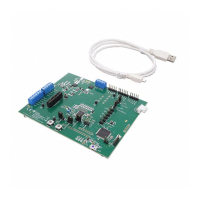
The bq76920 circuit module contains the bq76920 IC and related circuitry to demonstrate the features of
the IC. Surface mount FETs are provided for the high current path. A thermistor provides temperature
sensing on the board. Other components provide support for the IC and connections to the board. Basic
operation is described in the quick start guide. For details of the circuit, refer to the physical construction
section.
4.1 Cell Simulator
The EVM includes a resistive cell simulator made up of 200-Ω series resistors. The top section of the S3
switch connects the BATT+ node to the top of the resistor string. The bottom of the resistor string is
connected to BATT-. The individual cell taps are connected to the cell monitor signals by other sections of
the dip switch. When operating with a power supply all switch sections should be closed. When operating
with cells, all the dip switch sections should be open to prevent loading the cells and discharging the
battery. The cell simulator resistors are located on the bottom of the board and may become warm during
operation. The orange LED near the dip switch indicates the cell simulator has power.
4.2 Evaluating with Simulated Current
The quick start guide describes connection for basic operation. Providing more than recognizable current
in that configuration can require a power supply with a significant power rating. Applying a charge current
can damage some power supplies. Figure 6 shows a method to force current through the control path
without a high wattage power supply or special equipment. The load power supply should be set at a low
voltage in a constant current mode. Polarity can be reversed on the load supply to simulate a charge
current. The battery simulation supply should never be reversed.
11
SLVU924B–March 2014–Revised April 2014 bq76920 Evaluation Module User's Guide
Submit Documentation Feedback
Copyright © 2014, Texas Instruments Incorporated

 Loading...


