Home
Texas Instruments
Motherboard
bq76940
Texas Instruments bq76940 User Manual
5
of 1
of 1 rating
34 pages
Give review
Manual
Specs
To Next Page
To Next Page
To Previous Page
To Previous Page
Loading...
DSG
1
CHG
2
VSS
3
SDA
4
SCL
5
TS1
6
CAP1
7
REGOUT
8
REGSRC
9
BAT
10
NC
11
VC5
12
VC4
13
VC3
14
VC2
15
VC1
16
VC0
17
SRP
18
SRN
19
ALERT
20
U1
BQ7692000PW
1µF
C1
100
R5
5
4
1
2
3
6
J1
395021006
1µF
C2
1µF
C3
1µF
C4
1µF
C5
1µF
C6
100
R4
100
R6
100
R7
100
R8
100
R9
4.7µF
C16
2.2µF
C13
1.25V
D2
J2
108-0740-001
0.001
R11
100
R10
100
R12
0.1µF
C8
0.1µF
C9
0.1µF
C7
TP10
DNP
TP12
DNP
TP15
DNP
TP8
DNP
TP21
DNP
TP17
TP20
DNP
TP23
DNP
30V
D3
SMBJ30A-13-F
DNP
100
R14
100
R24
100
R25
499k
R13
4
1
2
3
J8
22-05-3041
10.0k
R23
10.0k
R21
TP19
1
2
J5
PEC02SAAN
1
2
J4
PEC02SAAN
J3
108-0740-001
600V
D7
MUR860G
DNP
4
7,8
1,2,3
5,6,
30V
Q1
CSD17501Q5A
4
7,8
1,2,3
5,6,
30V
Q2
CSD17501Q5A
600V
D6
MURS360T3G
1.00Meg
R19
1.00Meg
R15
GND
GND
GND
GND
GND
J6
108-0740-001
J7
108-0740-001
0.1µF
C11
0.1µF
C12
0.1µF
C17
0.1µF
C18
1µF
C14
0
R16
1.00k
R17
1.00Meg
R18
-50V
Q3
BSS84W-7-F
16V
D5
MMSZ5246B-7-F
DNP
1.25V
D4
GND
10.0k
Ω
t°
R20
4700pF
C15
GND
GND
TP9
DNP
TP11
DNP
TP13
DNP
TP14
DNP
TP7
DNP
TP18
DNP
TP24
DNP
TP27
DNP
TP26
DNP
TP25
DNP
TP22
DNP
NT1
Net-Tie
BATT–
GND
BATT
-
E2
E4
E3
E1
BATT–
1
2
3
4
S1
4-1437565-1
3.01k
R22
5.6V
D8
5.6V
D9
HS1
573300D00010G
DNP
TP3
TP4
TP5
TP6
TP1
DNP
TP2
DNP
TP29
DNP
TP28
DNP
GND
0
R2
DNP
0
R1
DNP
C5
C4
C3
C2
C1
C0
BAT
R
SCL
pull up
SDA
pull up
BATT+
10.0k
R3
–
Input voltage 0 - 25 V
0 - 15
A
+
–
Output voltage 0 - 25 V
0 - 15
A
+
28V
D1
SMCJ28A
100
R26
100
R27
ALERT
470pF
C10
DNP
DSG
CHG
CAP1
SDA
SCL
REGOUT
C1
C0
C1
C2
C3
C4
C5
BATT+
BATT+
PFD
PACK–
I
C
2
BOOT
TP16
bq76920EVM
Circuit
Module
Physical
Construction
www.ti.com
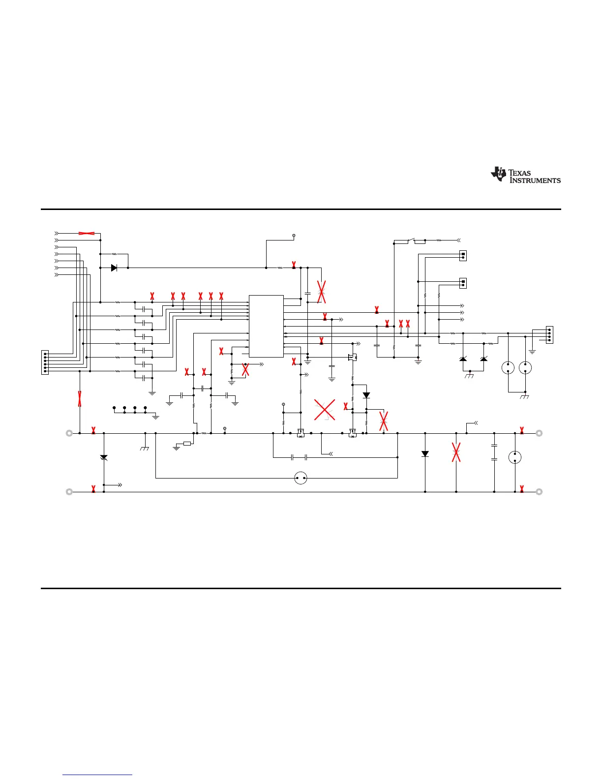
Figure
15
through
Figure
17
illustrate
the
schematics.
Figure
15.
Schematic
Diagram
AFE
26
bq76920
Evaluation
Module
User's
Guide
SLVU924B
–
March
2014
–
Revised
April
2014
Submit
Documentation
Feedback
Copyright
©
2014,
Texas
Instruments
Incorporated
25
27
Table of Contents
Table of Contents
1
Bq76920 Evaluation Module User's Guide
1
Features
2
Kit Contents
2
Ordering Information
2
Bq76920 Circuit Module Performance Specification Summary
3
Required Equipment
3
Bq76920 EVM Quick Start Guide
3
Before You Begin
3
SLVU924B – March 2014 – Revised April
3
Quick Start
4
Bq76940/Bq76930/Bq76920 Software
5
System Requirements
5
Installing the Bq76940/Bq76930/Bq76920 Software
5
Interface Adapter
5
EVM Connection for Basic Operation
5
Software Operation
6
Bq76940/Bq76930/Bq76920 Evaluation Software Display
6
Registers View
8
I2C Pro View
9
Sequence View
10
Bq76920 Circuit Module Use
11
Cell Simulator
11
Evaluating with Simulated Current
11
Reducing the Cell Count
12
Simulating Current Setup
12
Connecting Cells
13
Connecting to a Host
13
Gauge Circuits
13
Unused Components
13
Bq76920Evm Circuit Module Physical Construction
15
Board Layout
15
Top Silk Screen
15
Top Assembly
16
SLVU924B - March 2014 - Revised April 2014
16
Layer
18
Layer
19
Bottom Layer
20
Bottom Silk Screen
21
Bottom Assembly
22
Bill of Materials
23
Bq76920 Circuit Module
24
Bq76920 Circuit Module
25
Schematic Diagram AFE
26
Schematic Diagram Gauge
27
Schematic Diagram Cell Simulator
28
Related Documents from Texas Instruments
29
Important Notice
33
5
Based on 1 rating
Ask a question
Give review
Questions and Answers:
Need help?
Do you have a question about the Texas Instruments bq76940 and is the answer not in the manual?
Ask a question
Texas Instruments bq76940 Specifications
General
Brand
Texas Instruments
Model
bq76940
Category
Motherboard
Language
English
Related product manuals
Texas Instruments BQ79600-Q1
25 pages
Texas Instruments bq34110EVM-796
24 pages
Texas Instruments M-LVDS
32 pages
Texas Instruments EV2400
20 pages
Texas Instruments LMK04826
54 pages
Texas Instruments DRV425EVM
14 pages
Texas Instruments mmWaveICBoost
80 pages
Texas Instruments Tiva TM4C1294
34 pages
Texas Instruments ADS1298ECG-FE
57 pages
Texas Instruments CDCE6214-Q1EVM
27 pages
Texas Instruments ADS1256EVM-PDK
46 pages
C2000 F28003x Series
30 pages