www.ti.com
Features
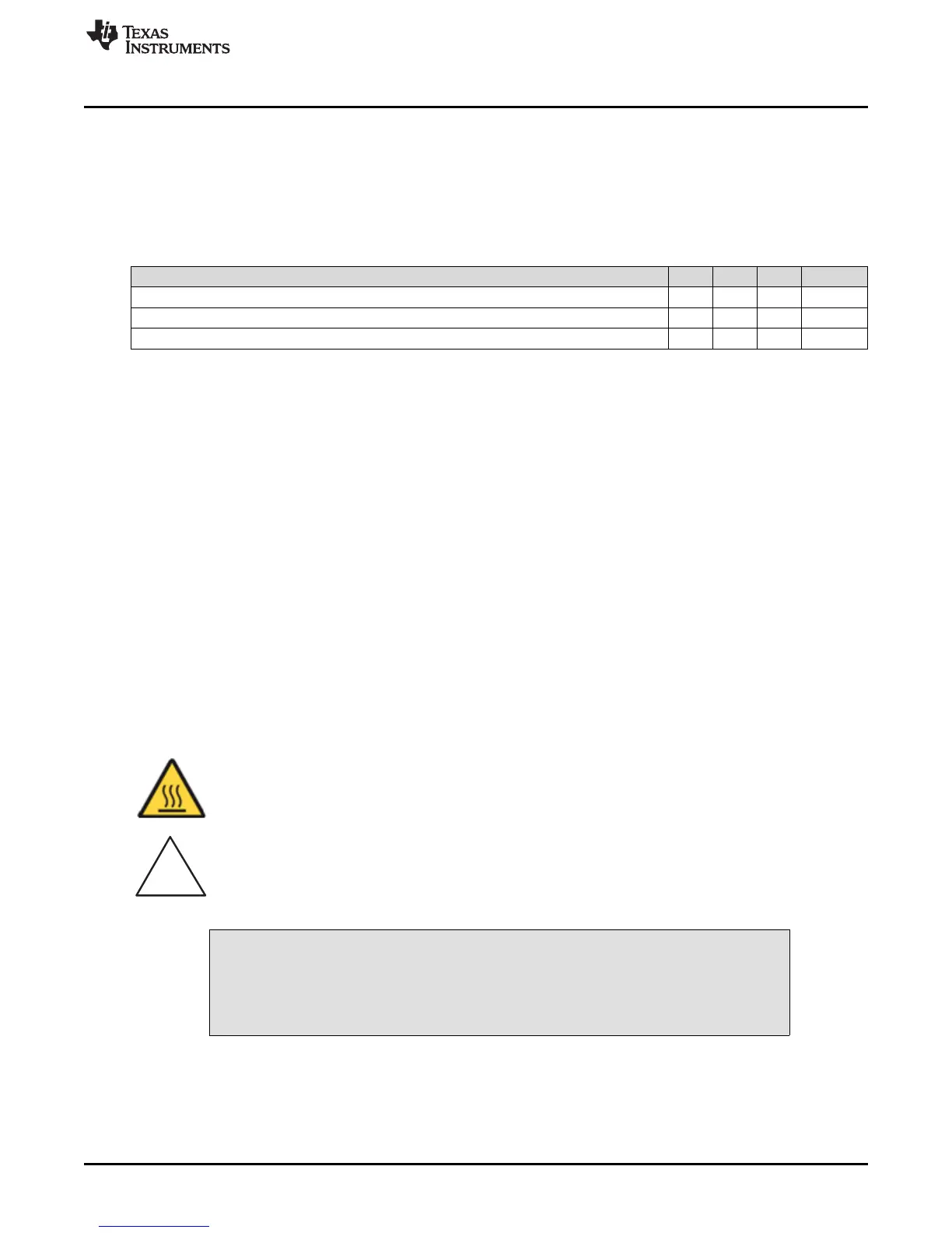
1.3 bq76920 Circuit Module Performance Specification Summary
This section summarizes the performance specifications of the bq76920 circuit module in its default 5-cell
parallel FET configuration.
Typical voltage depends on the number of cells configured. Typical current depends on the application.
Board cooling may be required for continuous operation at or below maximum current.
Table 2. Performance Specification Summary
Specification Min Typ Max Unit
Input voltage BATT+ with respect to BATT– 6 – 25 V
Continuous charge or discharge current 0 – 15 A
Operating temperature range 20 25 30 °C
1.4 Required Equipment
The following equipment is required to operate the bq76920 EVM in a simple demonstration:
• DC power supply, 0–25 V at 0.5 A
• DC voltmeter
• TI EV2300 or EV2400 interface board
• Computer with USB port and compatible Windows operating system and access to the internet
• TI bq76940/bq76930/bq76920 Evaluation Software (see Section 3)
• Test leads to connect equipment
• Electronic load or assorted resistors
Additional equipment may be desired to operate the bq76920 with a more extensive demonstration.
2 bq76920 EVM Quick Start Guide
2.1 Before You Begin
The following warnings and cautions are noted for the safety of anyone using or working close to the
bq76920 EVM. Observe all safety precautions.
Warning The bq76920EVM circuit module may become hot during
operation due to dissipation of heat. Avoid contact with the
board. Follow all applicable safety procedures applicable to
your laboratory.
Caution Do not leave the EVM powered when unattended.
CAUTION
The circuit module has signal traces, components, and component leads on the
bottom of the board. This may result in exposed voltages, hot surfaces or sharp
edges. Do not reach under the board during operation.
3
SLVU924B–March 2014–Revised April 2014 bq76920 Evaluation Module User's Guide
Submit Documentation Feedback
Copyright © 2014, Texas Instruments Incorporated