March 2009 SNAU028A 31
7.0. Powering the LMP90100EB
There are two ways in which VA and VIO can be sourced: external supplies or SPIO-4 power.
If using external power supplies to source VA and VIO, then do the following:
1. Connect an external power supply to J1 for VA. Jumper pins 1 and 2 of JP1 to select this option.
2. Connect an external power supply to J2 for VIO. Jumper pins 1 and 2 of JP2 to select this option.
3. Jumper JP6 to connect the external power to VA.
4. Jumper JP7 to connect the external power to VIO.
If using the SPIO-4 power to source VA and VIO, then do the following:
1. Jumper pins 1 and 2 of JP4 to select 3.3V for VA and VIO, or jumper pins 2 and 3 of JP4 to
select 5.0V for VA and VIO.
2. Jumper pins 2 and 3 of JP1 to select the SPIO-4 power for VA.
3. Jumper pins 2 and 3 of JP2 to select the SPIO-4 power for VIO.
4. Jumper JP6 to connect the SPIO-4 power to VA.
5. Jumper JP7 to connect the SPIO-4 power to VIO.
The schematic for the LMP90100EB can be seen in section 10.
8.0. Evaluating the LMP90100 without the SPIO-4 Board.
The SPIO-4 digital controller board is used to generate the SPI signals to communicate to the
LMP90100. Without the SPIO-4 board, the Sensor AFE software for the LMP90100 cannot be used
to capture and analyze data from the LMP90100EB.
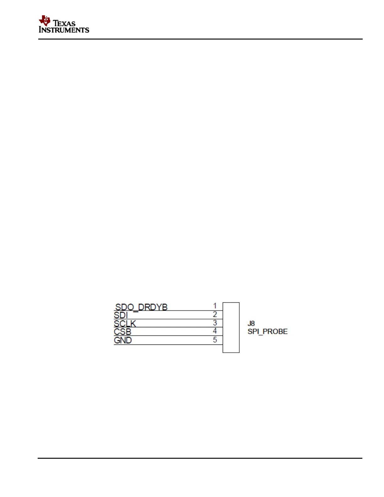
If the SPIO-4 board is not available but LMP90100 evaluation is desirable, then connect your own
SPI signals to J8 of the LMP90100EB as seen below.
Figure 30 - LMP90100EB’s J8 for SPI Signals
Refer to the LMP90100 datasheet for more information on the LMP90100’s SPI protocol.