Table 1 - Jumpers for DC Measurement
B. Installing/Opening the Software - follow section 9.0 to install and open the LMP90100 Sensor
AFE software.
C. Connecting and Powering the Boards – these steps have to be done in this order.
1. Connect a 5.0V power supply to J1 (VA_EXT) and GND (J2). Don’t turn on the power
supply yet.
2. Connect a 5.0V power supply to J3 (VIO_EXT) and GND (J2). Don’t turn on the power
supply yet.
3. Turn on the power supply that is sourcing VA (J1), and then turn on the power supply that is
sourcing VIO (J3).
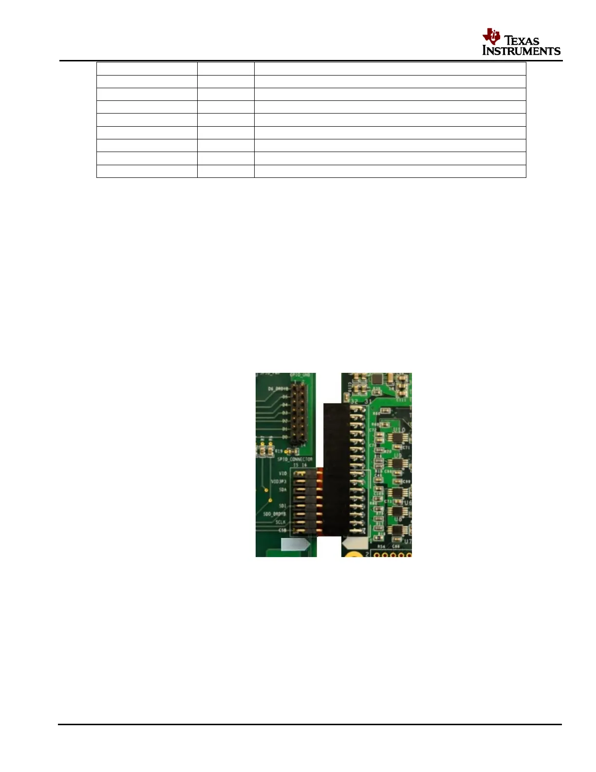
4. Connect the LMP90100EB’s JP12 to SPIO-4 Board’s J6 (pins 1-16). See Figure 4.
Figure 4 – LMP90100EB-to-SPIO-4 Board Connection
5. Connect SPIO-4 board to a PC via USB.
6. Use a multimeter to measure LMP90100EB’s JP6, JP7; they should all be approximately 5V.
If they are not, check your power supplies and jumpers. Measure JP14.P2; it should be
approximately 4.1V. If it’s not, check your jumpers and U4.
D. Configuring the LMP90100 Using the Sensor AFE Software