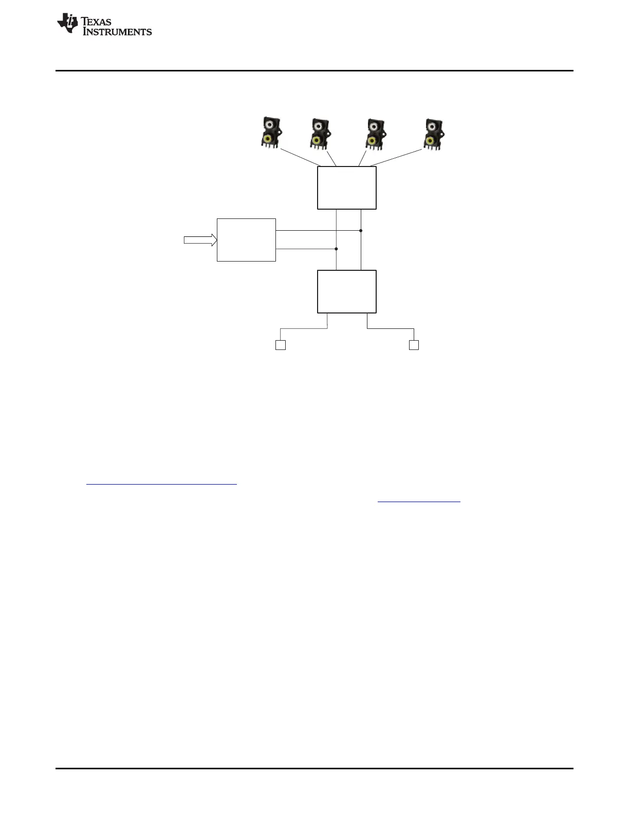
Vin1
PCM186x
Vin2
Vin3 Vin4
PCM9211
USB-I2X
USB
I2S
I2C
SPDIF
Opto In
SPDIF
Opto Out
www.ti.com
Getting Started
3.2 Block Diagram
Figure 4 shows a block diagram of the mated boards.
Figure 4. Block Diagram
The EVM has several different clocking options and can be run in one of three different modes. These
modes also control how the audio data is routed. The default mode is Mode 0, for more detail on the
available modes, refer to Section 4.3.
3.3 Software Download
The EVM is controlled through the PurePath™ Console. Request PurePath Console access here:
www.ti.com/tool/purepathconsole.
Once access is granted, download the PurePath Console here: http://cc.ext.ti.com
5
SLAU615–December 2014 PCM186xEVM
Submit Documentation Feedback
Copyright © 2014, Texas Instruments Incorporated