www.ti.com
Hardware
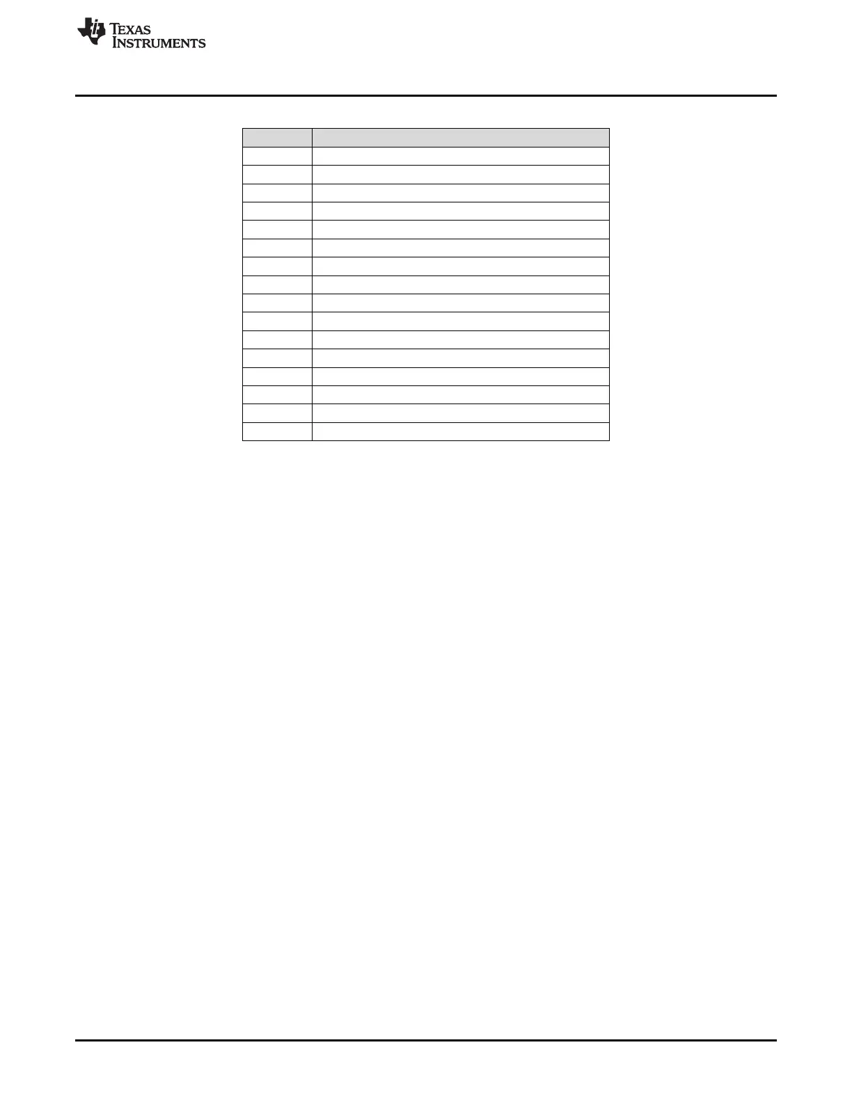
Table 2. J7 Controls
J7 Pin Description
1 MD0
2 Ground
3 MD1/AD
4 Ground
5 MD3/MC/SCL
6 Ground
7 Dout2/MD2/MOSI/SDA
8 Ground
9 MD4/MISO/GPIO
10 Ground
11 MD5/GPIO1/INTA/DMIN
12 Ground
13 MD6/GPIO2/INTB/DMCLK
14 Ground
15 INT/GPIO3/INTC
16 Ground
• J8 – J8 is used to enable or disable the Y0 crystal buffer. With the jumper inserted, this buffer is
disabled. With the jumper removed, the buffer is enabled.
• J9 – J9 is used to connect Mic Bias to the inputs for use with an electric microphone. If the jumper is
installed, the Mic Bias is connected to the inputs, if the jumper is removed, Mic Bias is disconnected.
• J10 – J10 is used to connect the crystal output (Y0) to a buffer. If the crystal output is being used,
insert J10.
• J11 – J11 is used to connect the Xi pin of the PCM186x to ground. If the crystal (Y0) is not used, Xi
should be grounded by inserting a jumper on J11. If the crystal is used, remove the J11 jumper.
• Opto Out – Opto out is the SPDIF output of the PCM9211.
• Y0 – Y0 is a socked crystal for the PCM186x. If using the PCM186x as the master, insert this crystal. If
the PCM186x is used as a slave, remove the crystal.
• Opto In – Opto in is the SPDIF input to the PCM9211. The PCM186x can mix this digital input with
ADC output.
7
SLAU615–December 2014 PCM186xEVM
Submit Documentation Feedback
Copyright © 2014, Texas Instruments Incorporated