Hardware
www.ti.com
4 Hardware
4.1 Power Requirements
The PCM186xEVM requires a 5-V power supply. This can be sourced from the I2X board via USB or
applied directly to the EVM on the +5-V header just above J1. Once 5 V is applied, the PCM186x board
regulates the 5 V down to a clean analog 3.3 V. A green LED just to the right of the 5-V header illuminates
if the voltages are present.
4.2 Connectors and Headers
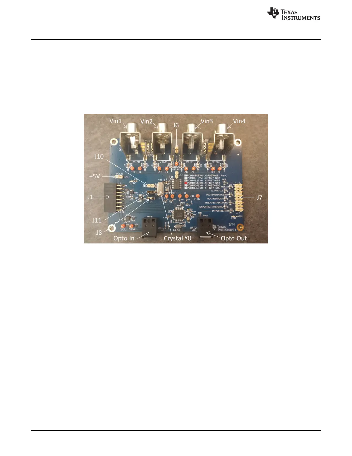
Figure 5. Diagram of Connector/Header Locations
• J1 – J1 is the I2X board connector. Provides I2C, I2S and +5 V connections to the PCM186x EVM.
• +5V – Input for power if no USB-I2X board is used. Output for +5 V, if USB-I2X board is used.
• Vin1 – Pins 3 (red-top input) and 4 (white-bottom input) of the PCM186x. AC coupled.
• Vin2 – Pins 1 (red-top input) and 2 (white-bottom input) of the PCM186x. AC coupled.
• Vin3 – Pins 30 (red-top input) and 29 (white-bottom input) of the PCM186x. AC coupled.
• Vin4 – Pins 28 (red-top input) and 27 (white-bottom input) of the PCM186x. AC coupled.
• J6 – J6 can be used to insert an external Mic Bias (remove J9).
• J7 – Most of the PCM186x GPIO, hardware control, and I2C signals are available here.
6
PCM186xEVM SLAU615–December 2014
Submit Documentation Feedback
Copyright © 2014, Texas Instruments Incorporated