1.1 Boot ROM Memory Map
Sin/Cos
(644 x 16)
Data space Prog space
Normalized inverse
(528 x 16)
Normalized square root
(274 x 16)
Normalized Arctan
(452 x 16)
(360 x 16)
Rounding and saturation
Bootloader functions
ROM version
ROM checksum
Reset vector
CPU vector table
(64 x 16)
On-chip boot ROM
Section start
address
0x3F F000
0x3F F502
0x3F F712
0x3F F9E8
0x3F FB50
0x3F F834
0x3F FFC0
0x3F FFFF
Boot ROM Memory Map
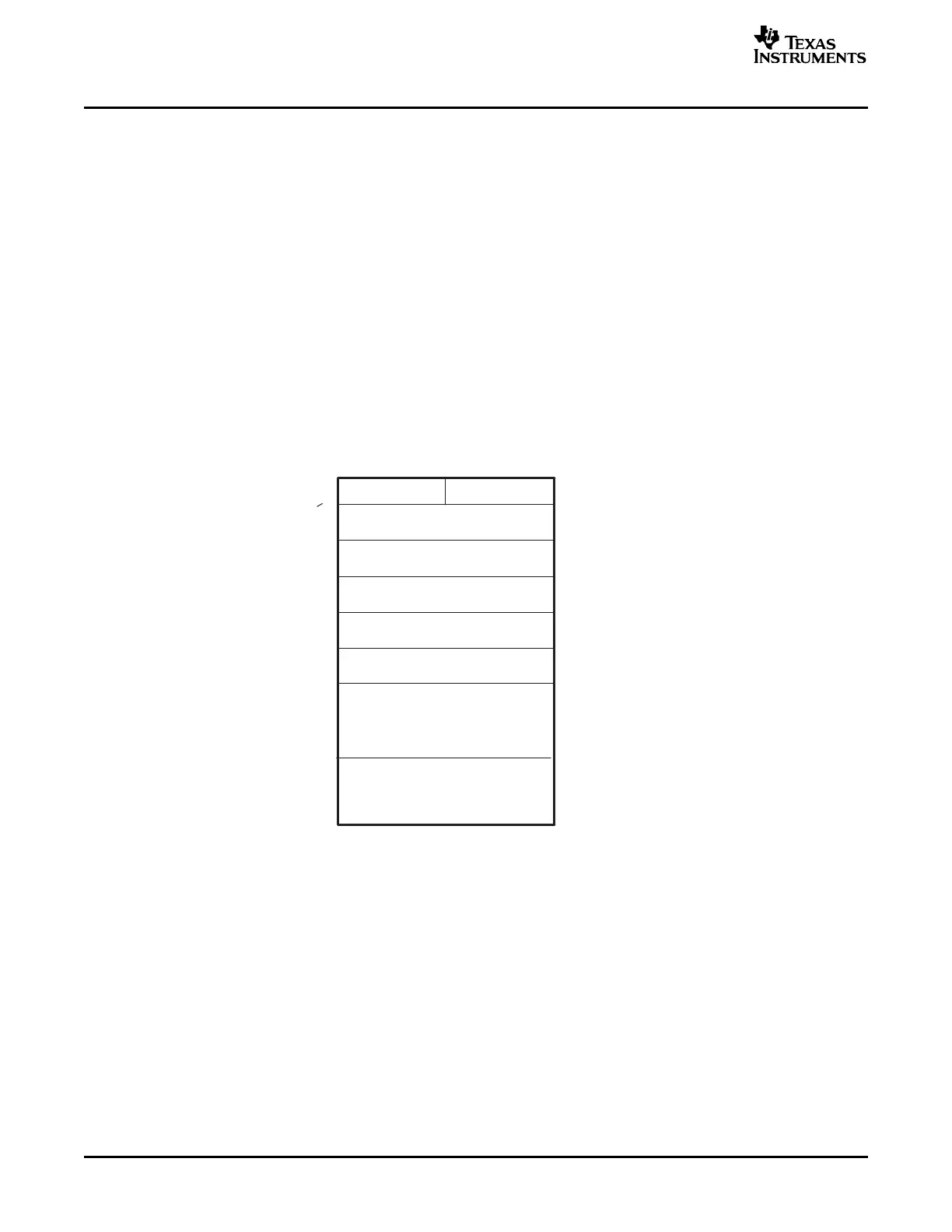
The boot ROM is a 4K x 16 block of read-only memory located at addresses 0x3F F000 - 0x3F FFF.
The on-chip boot ROM is factory programmed with boot-load routines and math tables for use with the
C28x™ IQMath Library - A Virtual Floating Point Engine (literature number SPRC087). Chapter 4 contains
the code for each of the following items:
• Bootloader functions
• Version number, release date and checksum
• Reset vector
• CPU vector table (Used for test purposes only)
• IQmath Tables
Figure 1-1 shows the memory map of the on-chip boot ROM. The memory block is 4Kx16 in size and is
located at 0x3F F000 - 0x3F FFFF in both program and data space.
Figure 1-1. Memory Map of On-Chip ROM
Boot ROM Overview12 SPRU722C – November 2004 – Revised October 2006
Submit Documentation Feedback
 Loading...


