2.17 SPI_Boot Function
SPISIMOA
SPISOMIA
SPICLKA
SPIESTEA
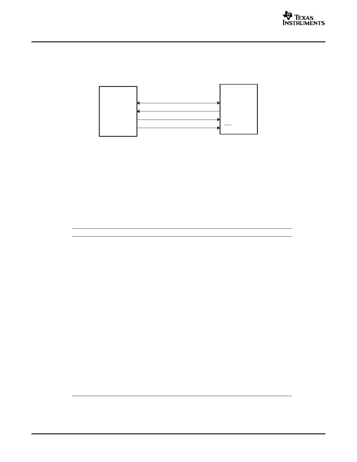
DIN
DOUT
CLK
CS
DSP
Serial SPI
EEPROM
SPI_Boot Function
The SPI loader expects an 8-bit wide SPI-compatible serial EEPROM device to be present on the SPI-A
pins as indicated in Figure 2-19 . The SPI bootloader does not support a 16-bit data stream.
Figure 2-19. SPI Loader
The SPI boot ROM loader initializes the SPI module to interface to a serial SPI EEPROM. Devices of this
type include, but are not limited to, the Xicor X25320 (4Kx8) and Xicor X25256 (32Kx8) SPI serial SPI
EEPROMs.
The SPI boot ROM loader initializes the SPI with the following settings: FIFO enabled, 8-bit character,
internal SPICLK master mode and talk mode, clock phase = 0, polarity = 0, using the slowest baud rate.
If the download is to be performed from an SPI port on another device, then that device must be setup to
operate in the slave mode and mimic a serial SPI EEPROM. Immediately after entering the SPI_Boot
function, the pin functions for the SPI pins are set to primary and the SPI is initialized. The initialization is
done at the slowest speed possible. Once the SPI is initialized and the key value read, you could specify a
change in baud rate or low speed peripheral clock.
Table 2-6. SPI 8-Bit Data Stream
Byte Contents
1 LSB: AA (KeyValue for memory width = 8-bits)
2 MSB: 08h (KeyValue for memory width = 8-bits)
3 LSB: LOSPCP
4 MSB: SPIBRR
5 LSB: reserved for future use
6 MSB: reserved for future use
... ...
... ...
17 LSB: reserved for future use
18 MSB: reserved for future use
19 LSB: Upper half (MSW) of Entry point PC[23:16]
20 MSB: Upper half (MSW) of Entry point PC[31:24] (Note: Always 0x00)
21 LSB: Lower half (LSW) of Entry point PC[7:0]
22 MSB: Lower half (LSW) of Entry point PC[15:8]
... ...
... ...
... Blocks of data in the format size/destination address/data as shown in the generic
data stream description
... ...
... ...
n LSB: 00h
n+1 MSB: 00h - indicates the end of the source
Bootloader Features40 SPRU722C – November 2004 – Revised October 2006
Submit Documentation Feedback
 Loading...


