2.1 Bootloader Functional Operation
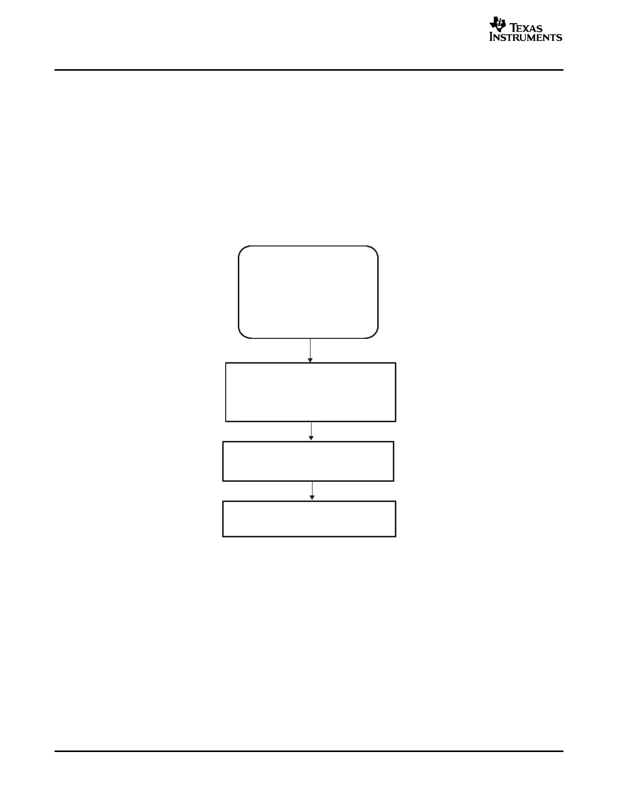
Boot ROM
Reset vector fetched from boot ROM
address 0x3F FFC0
Jump to InitBoot function to start
boot process
Boot determined by the state of I/O pins
SelectBootMode function
Begin execution at Entry Point as
determined by selected boot mode
PIE disabled (ENPIE−0)
VMAP=1
OBJMODE=0
AMODE=0
MOM1MAP=1
Reset
(power-on reset or warm reset)
Silicon sets the following:
Bootloader Functional Operation
The bootloader is the program located in the on-chip boot ROM that is executed following a reset.
The bootloader is used to transfer code from an external source into internal memory following power up.
This allows code to reside in slow non-volatile memory externally, and be transferred to high-speed
memory to be executed.
The bootloader provides a variety of different ways to download code to accommodate different system
requirements. The bootloader uses various GPIO signals to determine which boot mode to use. The boot
mode selection process as well as the specifics of each bootloader are described in the remainder of this
document. Figure 2-1 shows the basic bootloader flow.
Figure 2-1. Bootloader Flow Diagram
The reset vector in boot ROM redirects program execution to the InitBoot function. After performing device
initialization the bootloader will check the state of GPIO pins to determine which boot mode you want to
execute. Options include: jump to flash, jump to SARAM, jump to OTP, or call one of the on-chip boot
loading routines.
After the selection process and if the required boot loading is complete, the processor will continue
execution at an entry point determined by the boot mode selected. If a bootloader was called, then the
input stream loaded by the peripheral determines this entry address. This data stream is described in
Section 2.10 . If, instead, you choose to boot directly to flash, OTP, or SARAM, the entry address is
predefined for each of these memory blocks.
The following sections discuss in detail the different boot modes available and the process used for
loading data code into the device.
Bootloader Features18 SPRU722C – November 2004 – Revised October 2006
Submit Documentation Feedback
 Loading...


