2.20 ExitBoot Assembly Routine
Reset
InitBoot
Yes
No
Call
BootLoader
?
Call ExitBoot
Cleanup CPU
registers to default
value after reset*
Call
SelectBootMode
Call Boot Loader
Deallocate stack
(SP=0x400)
Branch to EntryPoint
Begin execution
at EntryPoint
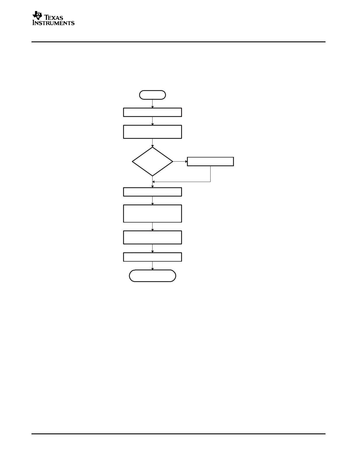
ExitBoot Assembly Routine
The Boot ROM includes an ExitBoot routine that restores the CPU registers to their default state at reset.
This is performed on all registers with one exception. The OBJMODE bit in ST1 is left set so that the
device remains configured for C28x operation. This flow is detailed in the following diagram:
Figure 2-27. ExitBoot Procedure Flow
The following CPU registers are restored to their default values:
• ACC = 0x0000 0000
• RPC = 0x0000 0000
• P = 0x0000 0000
• XT = 0x0000 0000
• ST0 = 0x0000
• ST1 = 0x0A0B
• XAR0 = XAR7 = 0x0000 0000
After the ExitBoot routine completes and the program flow is redirected to the entry point address, the
CPU registers will have the following values:
SPRU722C – November 2004 – Revised October 2006 Bootloader Features 47
Submit Documentation Feedback
 Loading...


