7.20 I
2
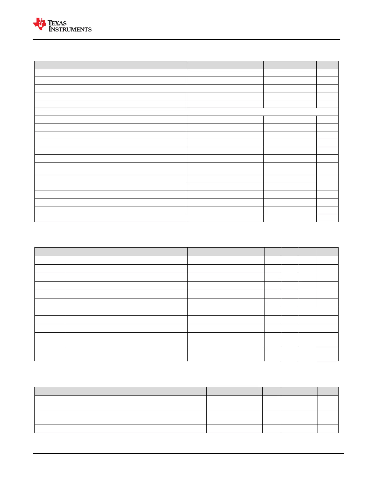
C Slave Characteristics (continued)
Recommended operating conditions; T
A
= –10 to 85°C unless otherwise noted
PARAMETER TEST CONDITIONS MIN TYP MAX UNIT
TOCF I
2
C output fall time 10 pF to 400 pF bus 250 ns
TBUF I
2
C bus free time between stop and start 4.7 μs
TSTS I
2
C start or repeated Start condition setup time 4.7 μs
TSTH I
2
C Start or repeated Start condition hold time 4 μs
TSPS I
2
C Stop condition setup time 4 μs
SDA and SCL FAST MODE CHARACTERISTICS
FSCL I
2
C clock frequency 0 400 kHz
THIGH I
2
C clock high time 0.6 μs
TLOW I
2
C clock low time 1.3 μs
TSUDAT I
2
C serial data setup time 100 ns
THDDAT I
2
C serial data hold time 0 ns
TVDDAT I
2
C valid data time SCL low to SDA output valid 0.9 μs
TVDACK I
2
C valid data time of ACK condition
ACK signal from SCL low to SDA (out)
low
0.9 μs
TOCF I
2
C output fall time
10 pF to 400 pF bus, VDD = 3.3 V 12 250
ns
10 pF to 400 pF bus, VDD = 1.8 V 6.5 250
TBUF I
2
C bus free time between stop and start 1.3 μs
TSTS I
2
Cstart or repeated Start condition setup time 0.6 μs
TSTH I
2
C Start or repeated Start condition hold time 0.6 μs
TSPS I
2
C Stop condition setup time 0.6 μs
7.21 SPI Controller Characteristics
Recommended operating conditions; T
A
= –10 to 85°C unless otherwise noted
PARAMETER TEST CONDITIONS MIN TYP MAX UNIT
FSPI Frequency of SPI_CLK 11.82 12 12.18 MHz
TPER Period of SPI_CLK (1/F_SPI) 82.1 83.33 84.6 ns
TWHI SPI_CLK High Width 30 ns
TWLO SPI_CLK Low Width 30 ns
TDACT SPI_SZZ falling to SPI_CLK rising delay time 30 50 ns
TDINACT SPI_CLK falling to SPI_CSZ rising delay time 160 180 ns
TDPICO SPI_CLK falling to SPI_PICO Valid delay time –5 5 ns
TSUPOCI SPI_POCI valid to SPI_CLK falling setup time 21 ns
THDPOCI SPI_CLK falling to SPI_POCI invalid hold time 0 ns
TRSPI SPI_CSZ/CLK/PICO rise time
10% to 90%, C
L
= 5 pF to 50 pF,
LDO_3V3 = 3.3 V
0.1 8 ns
TFSPI SPI_CSZ/CLK/PICO fall time
90% to 10%, C
L
= 5 pF to 50 pF,
LDO_3V3 = 3.3 V
0.1 8 ns
7.22 BUSPOWERZ Configuration Characteristics
Recommended operating conditions; T
A
= –10 to 85°C unless otherwise noted
PARAMETER TEST CONDITIONS MIN TYP MAX UNIT
VBPZ_EXT
BUSPOWERZ Voltage for receiving VBUS Power through the
PP_EXT path
0.8
V
VBPZ_HV
BUSPOWERZ Voltage for receiving VBUS Power through the
PP_HV path
0.8 2.4
V
VBPZ_DIS BUSPOWERZ Voltage for disabling system power from VBUS 2.4 V
www.ti.com
TPS65982
SLVSD02E – MARCH 2015 – REVISED AUGUST 2021
Copyright © 2021 Texas Instruments Incorporated
Submit Document Feedback
27
Product Folder Links: TPS65982