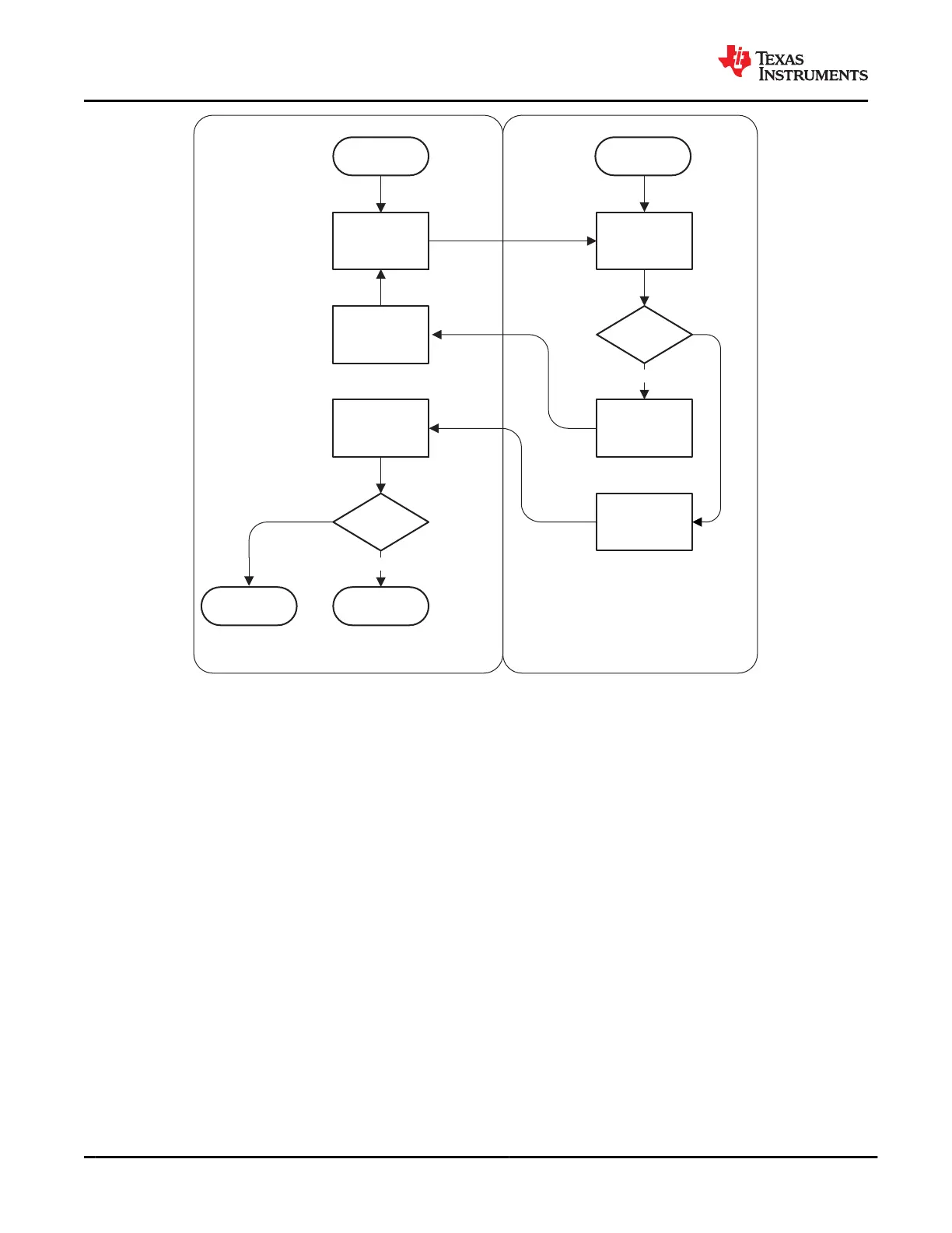
Send “Request
Data” Packet
Boot Fail
Receive “Send
Data” Packet &
Save Data
Receive “Send
CRC” packet
Saved Data
valid
Run App Code
Block map
complete
Send “Send Data”
packet
Send “Send CRC”
Packet
Receive “Request
Data” Packet
No
Yes
Yes
No
PrimarySecondary
SPI_POCI
Low
App Code Loaded
Figure 9-60. UART Download Process
9.5 Programming
9.5.1 SPI Controller Interface
The TPS65982 loads flash memory during the Boot Code sequence. The SPI Controller electrical characteristics
are defined in SPI Controller Characteristics and timing characteristics are defined in Figure 8-5. The TPS65982
is designed to power the flash from LDO_3V3 to support dead-battery or no-battery conditions, and therefore
pullup resistors used for the flash memory must be tied to LDO_3V3. The flash memory IC must support 12 MHz
SPI clock frequency. The size of the flash must be at least 1 Mbyte (equivalent to 8 Mbit) to hold the standard
application code outlined in Application Code. The SPI Controller of the TPS65982 supports SPI Mode 0. For
Mode 0, data delay is defined such that data is output on the same cycle as chip select (SPI_CSZ pin) becomes
active. The chip select polarity is active-low. The clock phase is defined such that data (on the SPI_POCI and
SPI_PICO pins) is shifted out on the falling edge of the clock (SPI_CLK pin) and data is sampled on the rising
edge of the clock. The clock polarity for chip select is defined such that when data is not being transferred
the SPI_CLK pin is held (or idling) low. The minimum erasable sector size of the flash must be 4 kB. The
W25Q80 flash memory IC is recommended. Refer to TPS65982 I
2
C Host Interface Specification for instructions
for interacting with the attached flash memory over SPI using the host interface of the TPS65982.
9.5.2 I
2
C Slave Interface
The TPS65982 has three I
2
C interface ports. I
2
C Port 1 is comprised of the I2C_SDA1, I2C_SCL1, and
I2C_IRQ1Z pins. I
2
C Port 2 is comprised of the I2C_SDA2, I2C_SCL2, and I2C_IRQ2Z pins. These interfaces
provide general status information about the TPS65982, as well as the ability to control the TPS65982
behavior, as well as providing information about connections detected at the USB-C receptacle and supporting
communications to and from a connected device, cable supporting BMC USB-PD, or both. The third port is
TPS65982
SLVSD02E – MARCH 2015 – REVISED AUGUST 2021
www.ti.com
76 Submit Document Feedback
Copyright © 2021 Texas Instruments Incorporated
Product Folder Links: TPS65982