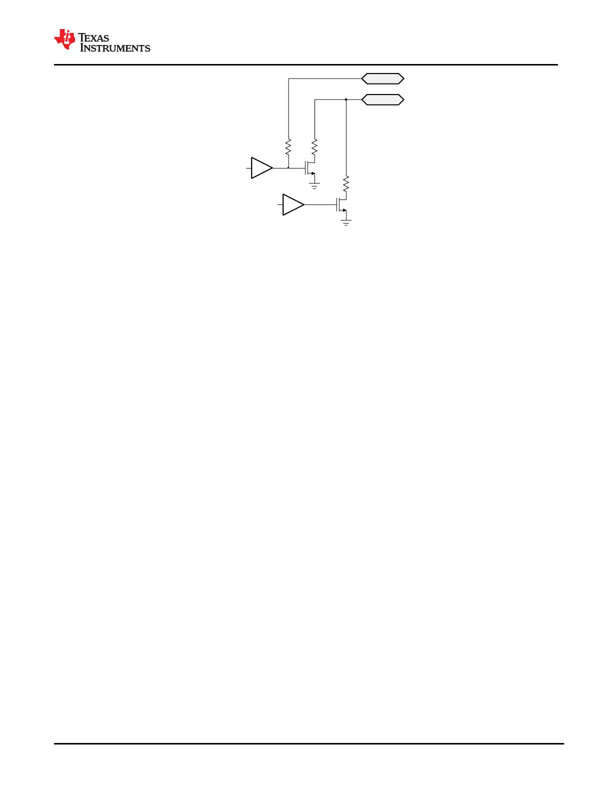
C_CCn
R_RPD RD_DB
RPD_Gn
RD_CC
RD_DB_EN
RD_CC_EN
Figure 9-10. C_CCn and RPD_Gn pins
When C_CC1 is shorted to RPD_G1 and C_CC2 is shorted to RPD_G2 in an application of the TPS65982,
booting from dead-battery or no-battery conditions will be supported. In this case, the gate driver for the pulldown
FET is Hi-Z at its output. When an external connection pulls up on C_CCn (the case when connected to a DFP
advertising with a pullup resistance Rp or pullup current), the connection through R_RPD will pull up on the FET
gate turning on the pulldown through RD_DB. In this condition, the C_CCn pin will act as a clamp VTH_DB in
series with the resistance RD_DB.
When RPD_G1 and RPD_G2 are shorted to GND in an application and not electrically connected to C_C1
and C_CC2, booting from dead-battery or no-battery conditions is not possible. In this case, the TPS65982 will
present a Hi-Z on the C_CC1 and C_CC2 pins and a USB Type-C source will never provide a voltage on VBUS.
9.3.3 Port Power Switches
Figure 9-11 shows the TPS65982 port power path including all internal and external paths. The port power path
provides to VBUS from PP_5V0, provides power to or from VBUS from or to PP_HV, provides power to or from
an external port power node (shown and refered to as PP_EXT) from or to VBUS, and provides power from
PP_CABLE to C_CC1 or C_CC2. The PP_CABLE to C_CCn switches shown in Figure 9-11 are the same as in
Figure 9-1, but are now shown without the analog USB Type-C cable plug and orientation detection circuitry.
www.ti.com
TPS65982
SLVSD02E – MARCH 2015 – REVISED AUGUST 2021
Copyright © 2021 Texas Instruments Incorporated
Submit Document Feedback
39
Product Folder Links: TPS65982