Table 9-1 shows the high-level detection results. Refer to the USB Type-C Specification for more information.
Table 9-1. Cable Detect States for a DFP
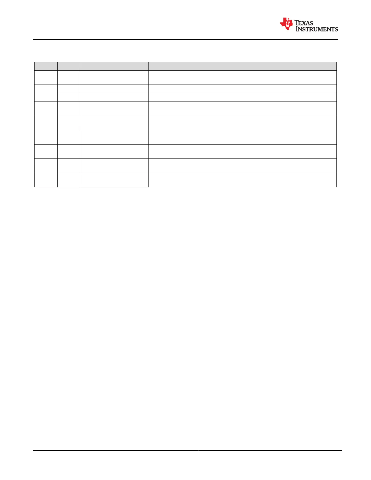
C_CC1 C_CC2 CONNECTION STATE RESULTING ACTION
Open Open Nothing attached
Continue monitoring both C_CC pins for attach. Power is not applied to VBUS or
VCONN until a UFP connect is detected.
Rd Open UFP attached Monitor C_CC1 for detach. Power is applied to VBUS but not to VCONN (C_CC2).
Open Rd UFP attached Monitor C_CC2 for detach. Power is applied to VBUS but not to VCONN (C_CC1).
Ra Open
Powered Cable/No UFP
attached
Monitor C_CC2 for a UFP attach and C_CC1 for cable detach. Power is not applied to
VBUS or VCONN (C_CC1) until a UFP attach is detected.
Open Ra
Powered Cable/No UFP
attached
Monitor C_CC1 for a UFP attach and C_CC2 for cable detach. Power is not applied to
VBUS or VCONN (C_CC1) until a UFP attach is detected.
Ra Rd Powered Cable/UFP Attached
Provide power on VBUS and VCONN (C_CC1) then monitor C_CC2 for a UFP
detach. C_CC1 is not monitored for a detach.
Rd Ra Powered Cable/UFP attached
Provide power on VBUS and VCONN (C_CC2) then monitor C_CC1 for a UFP
detach. C_CC2 is not monitored for a detach.
Rd Rd
Debug Accessory Mode
attached
Sense either C_CC pin for detach.
Ra Ra
Audio Adapter Accessory
Mode attached
Sense either C_CC pin for detach.
When the TPS65982 is configured as a DFP, a current IH_CC is driven out each C_CCn pin and each pin is
monitored for different states. When a UFP is attached to the pin, a pulldown resistance of Rd to GND will exist.
The current IH_CC is then forced across the resistance Rd generating a voltage at the C_CCn pin.
When configured as a DFP advertising Default USB current sourcing capability, the TPS65982 applies
IH_CC_USB to each C_CCn pin. When a UFP with a pulldown resistance Rd is attached, the voltage on the
C_CCn pin will pull below VH_CCD_USB. The TPS65982 can also be configured as a DFP to advertise default
(500 mA), 1.5 A and 3 A sourcing capabilities.
When the C_CCn pin is connected to an active cable VCONN (power to the active cable), the
pulldown resistance will be different (Ra). In this case, the voltage on the C_CCn pin will pull below
VH_CCA_USB/1P5/3P0 and the system will recognize the active cable.
The VH_CCD_USB/1P5/3P0 thresholds are monitored to detect a disconnection from each of these cases
respectively. When a connection has been recognized and the voltage on the C_CCn pin rises above the
VH_CCD_USB/1P5/3P0 threshold, the system will register a disconnection.
9.3.2.2 Configured as a UFP
When the TPS65982 is configured as a UFP, the TPS65982 presents a pulldown resistance RD_CC on each
C_CCn pin and waits for a DFP to attach and pullup the voltage on the pin. The DFP will pullup the C_CC pin
by applying either a resistance or a current. The UFP detects an attachment by the presence of VBUS. The UFP
determines the advertised current from the DFP by the pullup applied to the C_CCn pin.
9.3.2.3 Dead-Battery or No-Battery Support
Type-C USB ports require a sink to present Rd on the CC pin before a USB Type-C source will provide a voltage
on VBUS. The TPS65982 is hardware-configurable to present this Rd during a dead-battery or no-battery
condition. Additional circuitry provides a mechanism to turn off this Rd when the port is acting as a source.
Figure 9-10 shows the RPD_Gn pin used to configure the behavior of the C_CCn pins, and elaborates on
the basic cable plug and orientation detection block shown in Figure 9-9. RPD_G1 and RPD_G2 configure
C_CC1 and C_CC2 respectively. A resistance R_RPD is connected to the gate of the pulldown FET on each
C_CCn pin. This resistance must be pin-strapped externally to configure the C_CCn pin to behave in one of
two ways: present an Rd pulldown resistance or present a Hi-Z when the TPS65982 is unpowered. During
normal operation, RD will be RD_CC; however, while dead-battery or no-battery conditions exist, the resistance
is un-trimmed and will be RD_DB. When RD_DB is presented during dead-battery or no-battery, application
code will switch to RD_CC.
TPS65982
SLVSD02E – MARCH 2015 – REVISED AUGUST 2021
www.ti.com
38 Submit Document Feedback
Copyright © 2021 Texas Instruments Incorporated
Product Folder Links: TPS65982