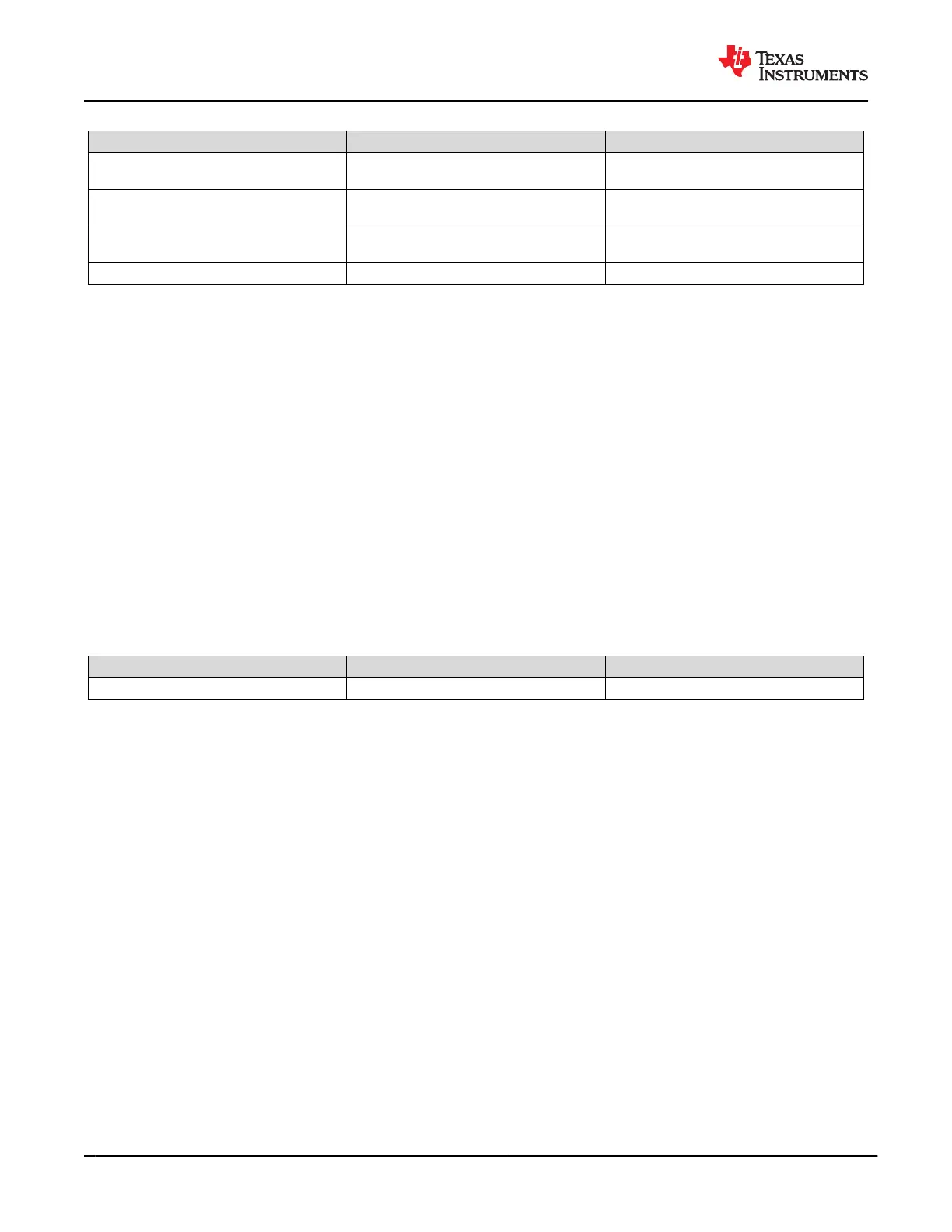
Table 10-1. Charging Application Design Parameters (continued)
DESIGN PARAMETER EXAMPLE VALUE DIRECTION OF CURRENT
PP_CABLE Input Voltage and Current
Capabilities
5 V, 500 mA Sourcing to VCONN
PP_HV Input Voltage and Current
Capabilities
12 V, 3 A Sourcing to VBUS
EXT FET Path Input Voltage and Current
Capabilities
20 V, 5 A Sourcing to VBUS
VIN_3V3 Voltage and Current Requirements 2.85 - 3.45 V, 50 mA Internal TPS65982 Circuitry
10.2.1.1.1 External FET Path Components (PP_EXT and RSENSE)
The external FET path allows for the maximum PD power profile (20 V at 5 A) and design considerations must
be taken into account for choosing the appropriate components to optimize performance.
Although a Type C PD charger will be providing power there could be a condition where a non-compliant device
can be connected to the charger and force voltage back into the charger. To protect against this the external FET
path detects reverse current in both directions of the current path. The TPS65982 uses two back-to-back NFETs
to protect both sides of the system. Another design consideration is to rate the external NFETs above the Type C
and PD specification maximum which is 20 V. In this specific design example, 30-V NFETs are used that have an
average R
DS,ON
of 5 mΩ to reduce losses.
The TPS65982 supports either a 10-mΩ or a 5-mΩ sense resistor on the external FET path. This RSENSE
resistor is used for current limiting and is used for the reverse current protection of the power path. A 5 mΩ
sense resistor is used in the design to minimize losses and I-R voltage drop. Recommended NFET Capabilities
summarizes the recommended parameters for the external NFET used. The total voltage drop seen across
RSENSE and the external NFET could be determined by Equation 5 below. It is important to consider the drop in
the entire system and regulate accordingly to ensure that the output voltage is within its specification. Equation 6
will calculate the power lost through the external FET path.
Table 10-2. Recommended NFET Capabilities
Voltage Rating Current Rating R
DS,ON
30 V (minimum) 10 A (peak current) < 10 mΩ
Voltage Drop = DC Current × (R
SENSE
+ NFET1 R
DS,ON
+ NFET2 R
DS,ON
)
(5)
Power Loss = Voltage Drop × DC Current
(6)
10.2.1.2 Detailed Design Procedure
10.2.1.2.1 TPS65982 External Flash
The external flash contains the TPS65982 application firmware and must be sized to 256kB minimum when the
flash is not shared with another IC, but a recommended minimum of 1 MB is needed when the flash memory of
the TPS65982 is shared with another IC. This size will allow for pointers and two copies of the firmware image to
reside on the flash along with the needed headers. The flash used is the W25Q80 which is a 3.3-V flash and is
powered from the LDO_3V3 output from the TPS65982.
10.2.1.2.2 I
2
C (I2C), Debug Control (DEBUG_CTL), and Single-Wire De-bugger (SWD) Resistors
I2C_ADDR, DEBUG_CTL1/2 pins must be tied to GND through a 0-Ω resistor tied to GND directly if needed
to reduce solution size. Pullups on the I2C_CLK, I2C_SDA, and I2C_IRQ are used for debugging purposes.
In most simple charger designs, I
2
C communication may not be needed. A 3.83-kΩ pullup resistor from
SWD_DATA to LDO_3V3 and a 100-kΩ pulldown resistor from SWD_CLK to GND must also be used for
debugging purposes.
10.2.1.2.3 Oscillator (R_OSC) Resistor
A 15-kΩ 0.1% resistor is needed for key PD BMC communication timing and the USB2.0 endpoint. A 1% 15-kΩ
resistor is not recommended to be used because the internal oscillators will not be controlled well enough by this
loose resistor tolerance.
TPS65982
SLVSD02E – MARCH 2015 – REVISED AUGUST 2021
www.ti.com
82 Submit Document Feedback
Copyright © 2021 Texas Instruments Incorporated
Product Folder Links: TPS65982