www.ti.com
XDS110 Adaptors
25
SPRUI94–January 2017
Submit Documentation Feedback
Copyright © 2017, Texas Instruments Incorporated
XDS110 Debug Probe
4 XDS110 Adaptors
4.1 Debug Connection Adaptors
4.1.1 Supported Debug Adaptors
The XDS110 supports a native CTI-20 debug connector. The product also supplies adaptor boards that
support adapting to the following on-board debug connectors:
• ARM Cortex-M 20-pin (CM20)
• ARM Cortex-M 10-pin (CM10)
• TI Legacy 14-pin (TI14)
4.1.2 Debug Adaptor Pin Mapping
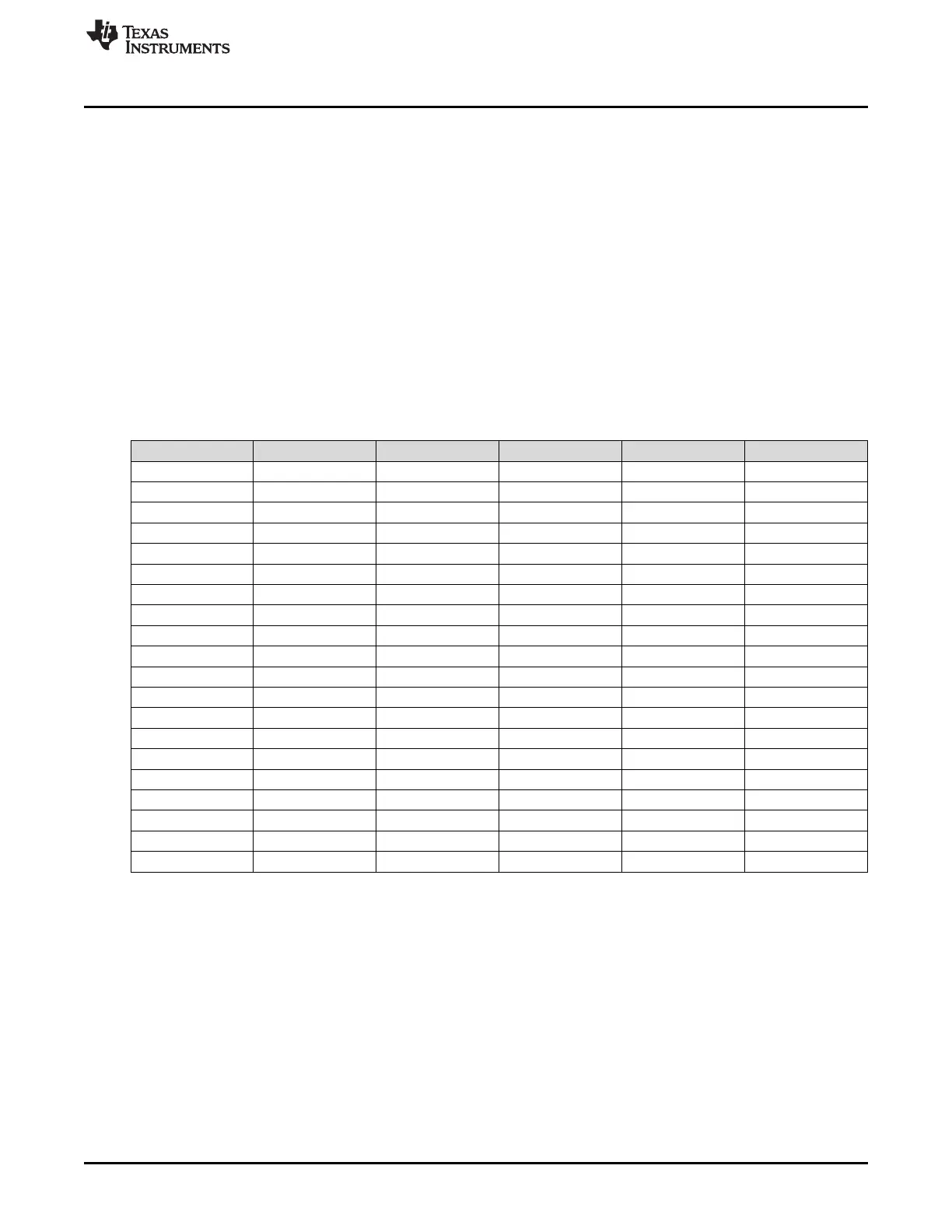
Table 4 defines the signal mapping used for each adaptor type.
(1)
Any signal not listed in this table is not connected through the adaptor.
Table 4. CTI to Other Adaptor Pin Mapping
Signal XDS110 Pin CTI20 Pin CM20 Pin
(1)
CM10 Pin
(1)
TI14 Pin
SWDIO/TMS 1 1 2 2 1
TRSTn 2 2 2
TDI 3 3 8 8 3
TDIS 4 4 4
VTREF 5 5 1 1 5
KEY 6 6 7 7 6
TDO/SWO 7 7 6 6 7
GND 8 8 3,5,9,11,15,17,19 3,5,9 8
RTCK 9 9
GND 10 10 10
SWCLK/TCK 11 11 4 4 11
GND 12 12 12
EMU0/TRIGOUT0 13 13 13
EMU1/TRIGOUT1 14 14 14
nRESET 15 15 10 10
GND 16 16
EMU2/TRIGIN0 17 17
EMU3/TRIGIN1 18 18
EMU4 19
NC 20 20
4.2 Auxiliary Connection Breakout Board
The XDS110 probe product also ships with a breakout board for the auxiliary (AUX) signals, so that
boards without a native AUX connection can be wired into the functions supported through this interface.
4.2.1 Auxiliary Breakout Board Pin Mapping
Table 5 defines the signal mapping used for the 12-pin inline stake connector of the breakout board.