Debug Control
MCU
Energy
Trace
Subsystem
USB
Interface
Voltage Translation
Expansion Interface
Target Debug Connection
Target Auxiliary Connection
USB Host Connection
JTAG
cJTAG
SWD
Reset
SWO
XDS110
Probe
UART
Power
GPIO
Target
System
(DUT)
Overview
www.ti.com
6
SPRUI94–January 2017
Submit Documentation Feedback
Copyright © 2017, Texas Instruments Incorporated
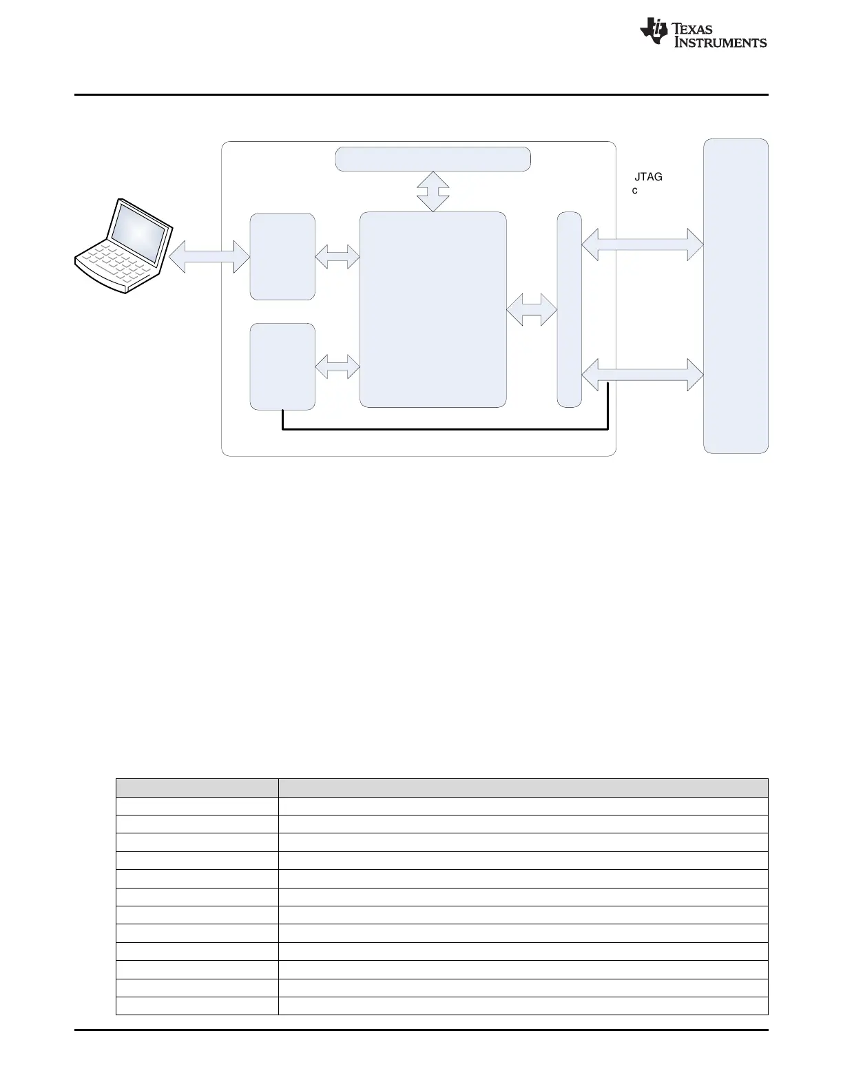
XDS110 Debug Probe
Figure 1. XDS110 Probe High-Level Block Diagram
1.5 XDS110 Parts List
The XDS110 debug probe system consists of the following hardware:
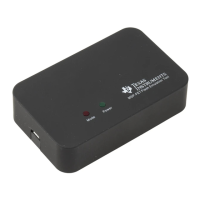
• The XDS110 debug probe
• One USB cable with Type-A female host connector and micro-B female connector for the probe
• One debug connection cable with CompactTI 20-pin connector (CTI-20)
• One auxiliary connection cable with 14-pin header
• One CTI-20 to Cortex-M 20-pin adaptor
• One CTI-20 to Cortex-M 10-pin adaptor
• One CTI-20 to TI 14-pin adaptor
• One 14-signal AUX breakout adaptor
1.6 Acronyms, Abbreviations, and Definitions
Table 1 shows the common acronyms and abbreviations used in this document.
Table 1. Acronyms and Definitions
Acronym Definition
cJTAG Compact JTAG
CAN Controller area network
CMSIS-DAP Cortex microcontroller software interface standard – debug access port
ET Energy trace
GPIO General purpose input output
HS High speed
IDC Insulation-displacement connector
JTAG Joint test action group
OTG On the go
SSI Synchronous serial interface
SWCLK Serial wire clock
SWD Serial wire debug