www.ti.com
Probe Interfaces
9
SPRUI94–January 2017
Submit Documentation Feedback
Copyright © 2017, Texas Instruments Incorporated
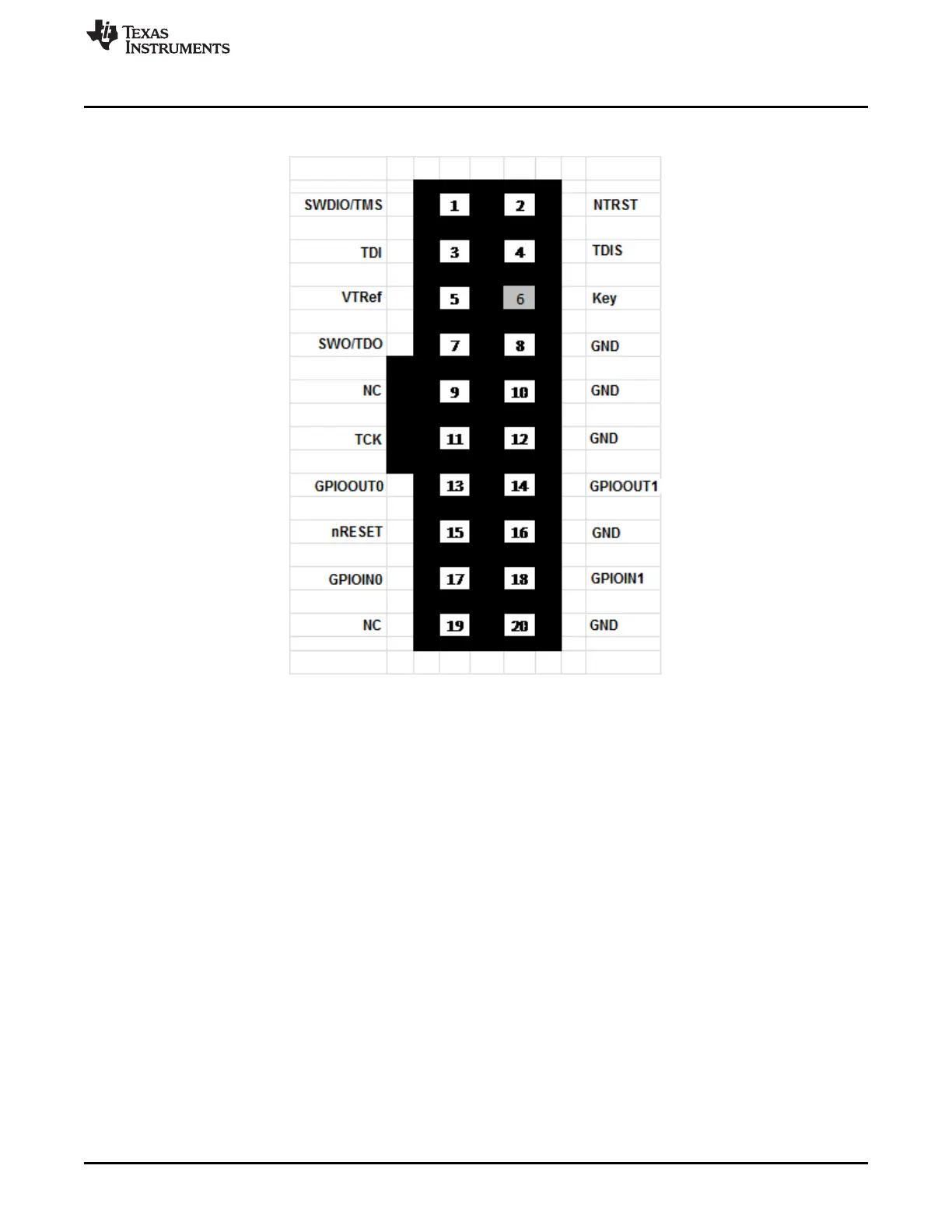
XDS110 Debug Probe
Figure 2. Debug Connection (CTI-20) Pin Mapping
2.4 Auxiliary Debug Interface
The XDS110 probe supports an auxiliary interface (AUX) for additional debug features through a second
14-signal cable and connector (see Section 2.4.1). Many of the AUX features and functions are not
available on the standard CTI-20 connector. These additional features include:
• A probe/target UART
• Probe-supplied target power
May be monitored for ET
• Target power supply input
May be looped back to the Target after monitoring for ET
• Four GPIO signals
– 2 × Probe to target
– 2 × Target to probe
– These signals are replicated the CTI-20 connector, but are also present for scenarios where
adaptors on the CTI-20 are supporting debug connections without GPIO capability.
2.4.1 Physical Connection for AUX
The AUX connection is a 14-pin IDC connection using .05 inch pitch. It is Samtec FFSD-compatible, with
the female connector on both ends. The pin mapping is shown in Figure 3.