Probe Interfaces
www.ti.com
8
SPRUI94–January 2017
Submit Documentation Feedback
Copyright © 2017, Texas Instruments Incorporated
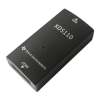
XDS110 Debug Probe
2 Probe Interfaces
The XDS110 probe supports a number of interfaces for host and target communication.
2.1 Supported Communication Protocols
The XDS110 probe supports the following industry standard interfaces for host to probe and probe to
target communications:
• Host to probe communication
– USB 2.0 device with HS USB PHY
– USB Communication Device Class protocol used for UART support
– Standard USB Bulk IN and OUT endpoints support TI custom protocols
• Probe to target communications
– IEEE 1149.1 JTAG
– IEEE 1149.7 cJTAG
– ARM serial wire debug (SWD)
– ARM serial wire output (SWO) – UART mode only
– Transmit and receive UARTs with RS-232C signaling – no hardware handshakes
2.2 USB
Host to probe communication is accomplished through a USB link. The probe has a female micro-USB B
type connector. The probe functions as a USB device only (no host mode or OTG). Power for the XDS110
probe is sourced from the USB V
BUS
(+5 V).
2.3 Debug Interface
The XDS110 probe supports a debug connection interface through the standard CTI-20 connector (see
Section 2.3.1). The supported debug features include:
• 5-pin 1149.1 JTAG connection (including TRSTn)
• 2-pin 1149.1 cJTAG connection
• 2-pin ARM SWD connection
• 1-pin SWO overlaid on JTAG TDO
• Target system reset
• Target voltage detect
• Target disconnect detect
• Four EMU signals for GPIO
– 2 × Probe to target
– 2 × Target to probe
– These signals are replicated on the AUX connector because many of the debug adaptors for CTI-
20 do not support connections with GPIO.
2.3.1 Physical Connection for Debug
The CTI-20 connection is a 20-pin IDC connection using .050 by .100 inch pitch. The pin mapping is
shown in Figure 2.