Cinterion
®
LGA DevKit User Guide
9.3 Errata/Troubleshooting
35
t lga_devkit_ug_v03 2020-05-29
Public / Released
Page 35 of 36
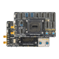
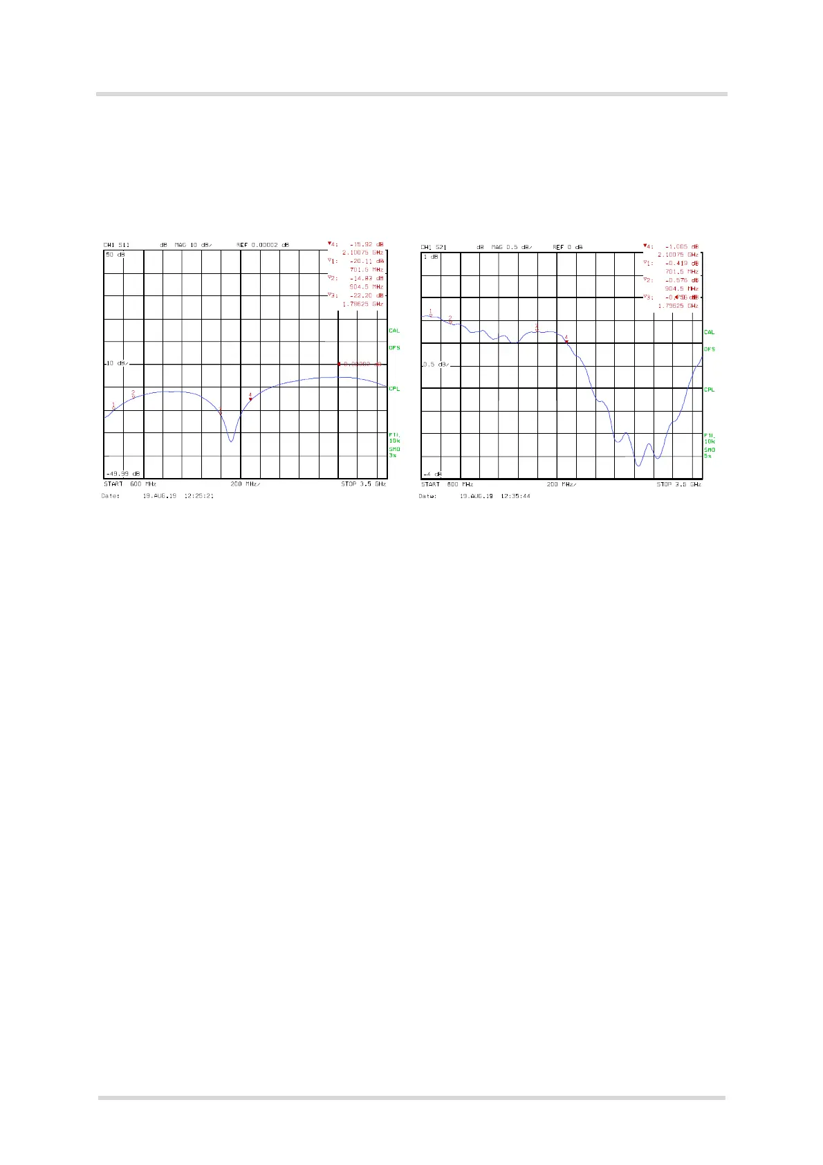
The old LGA DevKit socket has a decreased RF matching that is improved with the new socket.
The below Figure 20 and Figure 21 shows measurements with the old LGA DevKit socket re-
garding the S11 DevKit's MAIN antenna module RF path as well as the S21 DevKit's MAIN an-
tenna RF path loss. Measurement results for the new LGA DevKit socket are shown above in
Section 4.11.
Figure 20: S11 MAIN antenna input return loss transmit
direction (with old socket)
Figure 21: S21 MAIN antenna insertion loss transmit
direction (with old socket)