THERMAL INNOVATIONS (UK) LTD | THERMAFLOW® ELECTRIC COMBINATION BOILER | Tel: 0870 850 5207
24
PART 3 - SERVICING
3.1. Fault Finding
MUST BE CARRIED OUT BY A PERSON COMPETENT TO DO SO
Before trying to operate the boiler make sure that:
The heating system pressure is at 120 KPA (1.2 Bar) when the system is cold and 200 KPA (2.0 Bar)
when the system is at maximum temperature.
There is a permanent mains power, (24hr supply) to the terminals marked in the controls enclosure at
the bottom of the boiler (Marked No 10-1 on the boiler schematic diagram 1.8.1).
There is power at the off peak (Interrupted) supply main switch in the lower enclosure at the top of the
boiler (Marked No 3 on the boiler schematic diagram 1.8.1).
WARNING: BEFORE OBTAINING ACCESS TO TERMINALS, ALL SUPPLY CIRCUITS MUST
BE DISCONNECTED.
IMPORTANT:
ON COMPLETION OF THE FAULT FINDING TASK WHICH HAS REQUIRED THE
BREAKING OR REMAKING OF THE ELECTRICAL CONNECTIONS, THE CONTINUITY,
POLARITY, SHORT CIRCUIT AND RESISTANCE TO EARTH CHECKS MUST BE REPEATED
USING A SUITABLE MULTI- METER.
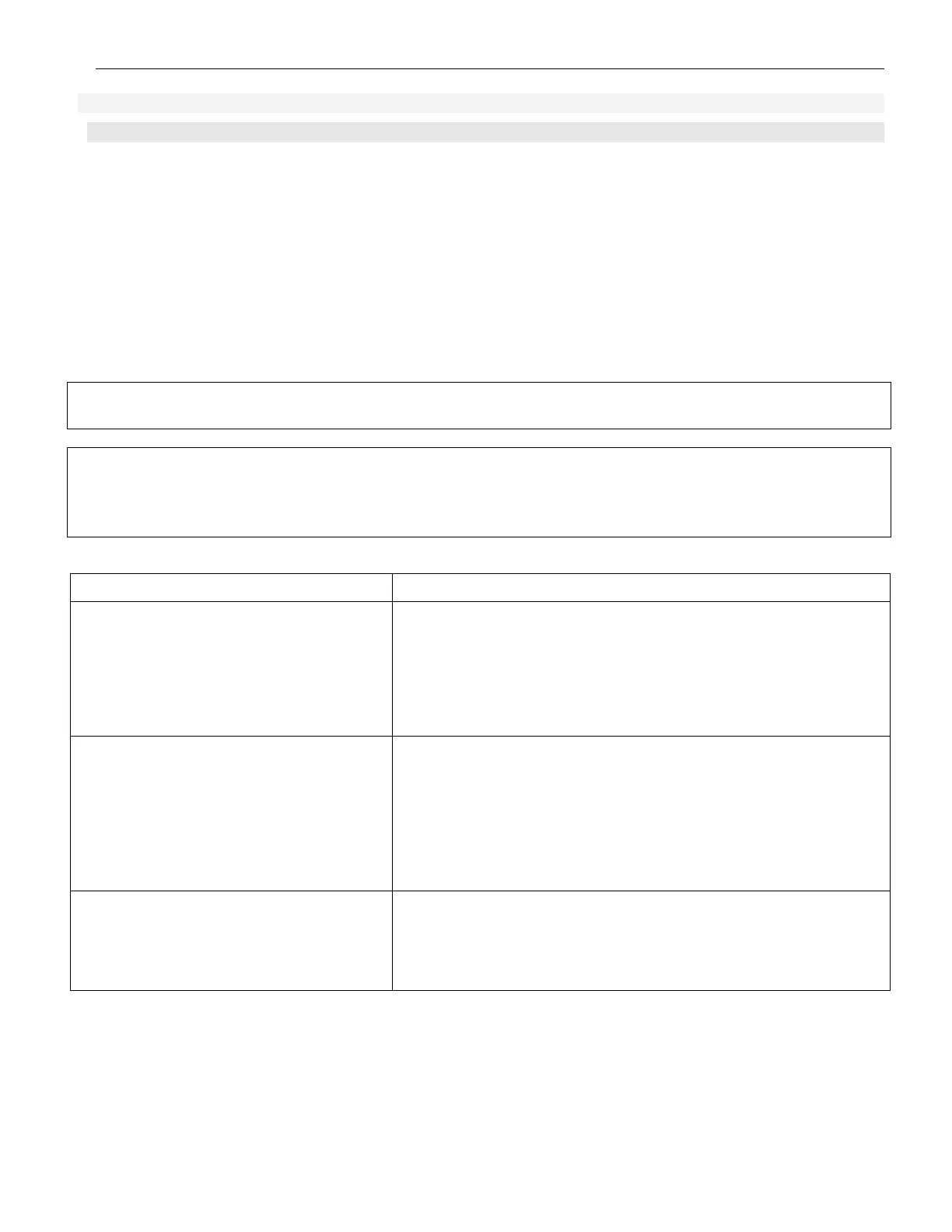
Type of fault
Check
No domestic hot water or central heating ~230-240V Supply (24HR)
~230-240V Supply (Off Peak)
System water pressure
Master high limit thermostat
Contactor
Reset-able Over Heat Thermostats
Heating elements
No central heating but hot water at taps
~230-240V Supply (24HR)
~230-240V Supply (Off Peak)
External controls
Heating elements
Reset-able Over Heat Thermostats
Temperature at bottom of store
must be above aqua stat setting
of 30ºC
Central heating pump
Central heating but no hot water at taps
or temperature diminishes after a short
period
Auto air eliminator in closed position
Pump valves in the open position?
Flow Switch
Relay (Enclosure 3, Diagram 1.8.1)
Domestic hot water pump