THERMAL INNOVATIONS (UK) LTD | THERMAFLOW® ELECTRIC COMBINATION BOILER | Tel: 0870 850 5207
Diagram 2.6.2b
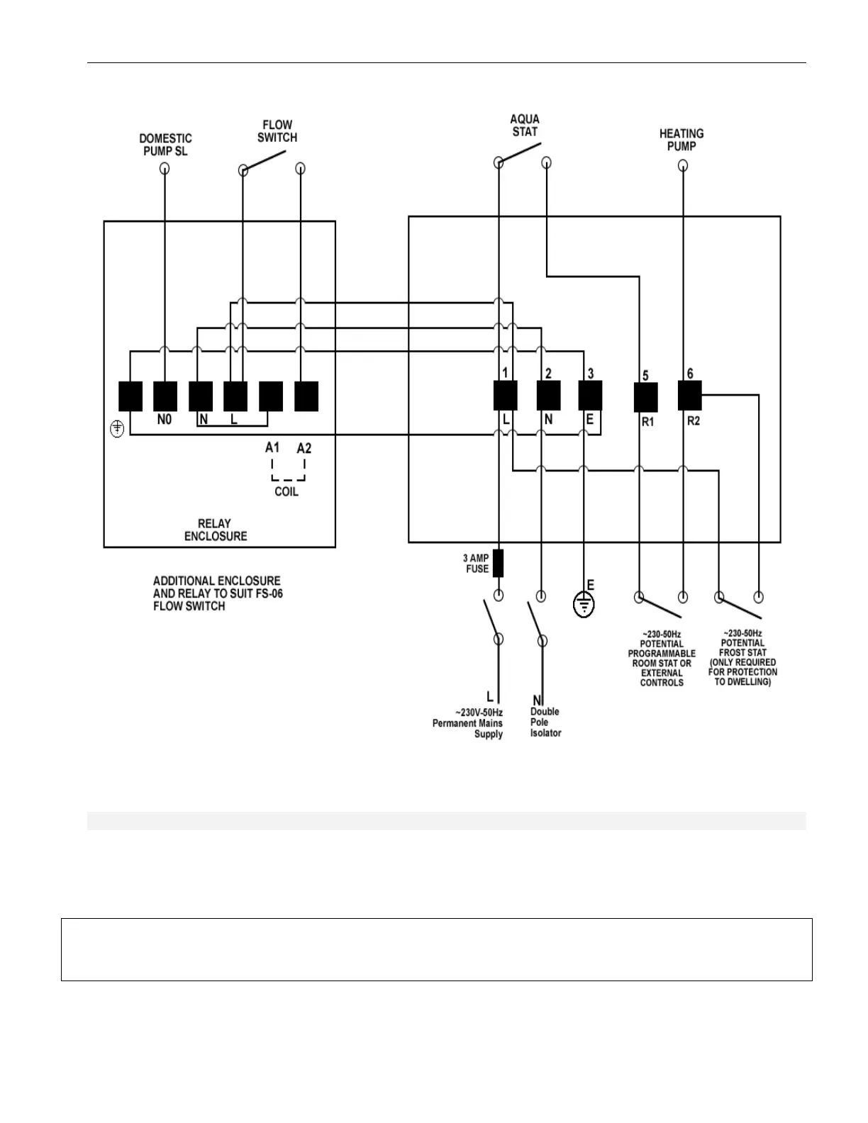
2.6.3 External Controls
External heating controls should be connected to the terminals marked R1 & R2 shown in
diagram
2.6.2b
. All external controls should be connected to terminals marked R1 & R2 in the enclosure marked
No 22 in the boiler schematic diagram 1.8.1.
WARNING: ALL EXTERNAL CONTROLS MUST NOT BE TAKEN FROM ANY OTHER
POWER SUPPLY OTHER THAN VIA THE
3 AMP FUSED ISOLATING SWITCH MENTIONED ABOVE.
19