THERMAL INNOVATIONS (UK) LTD | THERMAFLOW® ELECTRIC COMBINATION BOILER | Tel: 0870 850 5207
1.8 GENERAL DATA
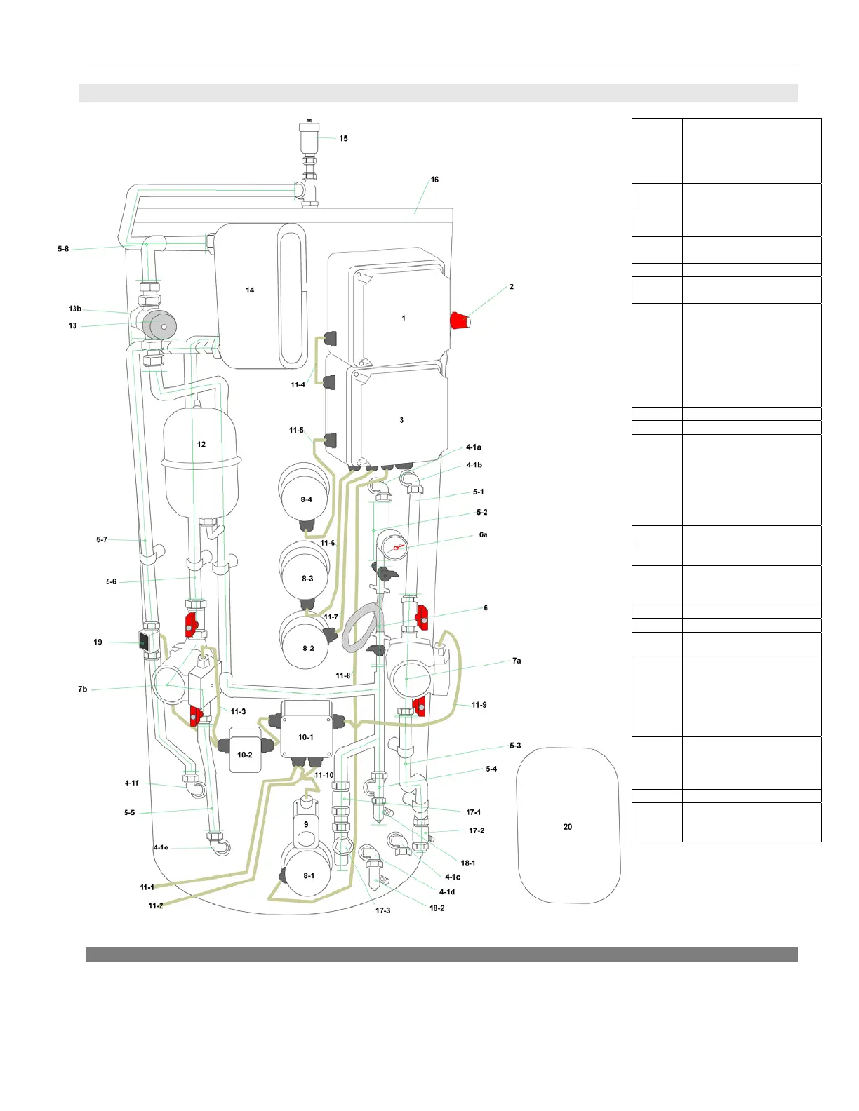
Diagram 1.8.1
1 Enclosure for Low
Pressure cut-out switch
& Master non-reset-able
over-temperature
thermostat
2 Safety Relief Valve
300kPA (3bar)
3 Enclosure for Contactor
and Circuit Breakers
4 22mm Compression
bends DZR
5 Pipe work
6 Filling Loop Assembly
6a Pressure gauge
7 Circulating Pumps
Complete with Isolating
Valves.
7a – Central Heating
Pump
7b – Grundfos
circulating pump HW
circuit
8 Heating Elements
9 Aqua Thermostat
10 10-1 Enclosure for
incoming live supply,
central heating pump &
Aqua stat
10-2 Enclosure for flow
switch relay & pump for
domestic HW circuit
11 Heat Resistant Flex
12 1 or 2 Litre Potable
expansion vessel
13 Thermostatic Blending
Valve
13b HW outlet
14 Plate Heat Exchanger
15 Automatic Air Eliminator
16 Stainless Steel Primary
Store
17 17-1 Single check valve
– cold water inlet
17-2 Single check valve
– CH flow
17-3 Y-pattern strainer
(cold water inlet)
18 18-1 Drain point
(potable)
18-2 Drain point
(primary)
19 Flow switch
20 Primary Expansion
vessel – connect into
CH return at boiler
Unit Design (Protected by Design Rights)
9