THERMAL INNOVATIONS (UK) LTD | THERMAFLOW® ELECTRIC COMBINATION BOILER | Tel: 0870 850 5207
4
0.1 Instructions general
A pressure reducing valve must be fitted to the cold water inlet if the incoming water pressure exceeds
400 KPA (4.0 Bar).
The primary operating pressure initial charge is 120 KPA (1.2Bar) this will increase to around 200 KPA
(2.0Bar) when the system has reached maximum temperature and will depend on system volume.
The primary expansion vessel pre-charge pressure is 150 KPA (1.5 Bar) and has volume of 25 and 35
litres depending on the model of boiler.
The secondary expansion vessel pre-charge pressure is 350 KPA (3.5 Bar) and has a volume of 1 or 2
litres.
The primary pressure relief valve is set to 300 KPA (3.0 Bar).
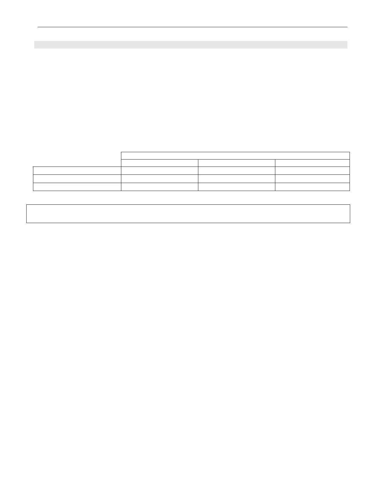
Thermaflow Model Number
TH9/21OU & TH12/210U TH9/250U & TH12/250U TH9/330U & TH12/330U
Primary storage capacity 210 litres 250 Litres 330 Litres
Weight when Empty 60KG 65KG 75KG
Weight when Full 270KG 315KG 405KG
WARNING: BEFORE OBTAINING ACCESS TO TERMINALS, ALL SUPPLY CIRCUITS MUST
BE DISCONNECTED.
The TH9/21OU, TH9/25OU and TH9/330U all have 3 heating elements fitted. Size 16” in length and are
manufactured of incaloy EN60335.2.73.
The rated power input of the appliance is ~230- 240V, 50Hz, 8,250-9,000w
The TH12/210U, TH12/250U and TH12/330U all have 4 heating elements fitted. Size 16” in length and
are manufactured of Incaloy EN60335.2.73.
The rated power input of the appliance is ~230-240V, 50Hz, 11,000-12,000w
The elements fitted to the Thermaflow should NOT be replaced with elements which have no thermal
cut outs
.
It is recommended that the Thermaflow has a safety and maintenance check on an annual basis.
A pressure reducing valve must be fitted to the cold water inlet of the appliance if the incoming
pressure exceeds 400kPA (4 Bar).
The position of the Tundish (IF REQUIRED) shall be visible to the occupants and shall be
positioned away from any electrical devices.
The position of discharge pipes, (Tundish), drain valves and motorised valves etc, must be
positioned away from electrical components.
The water may drip from the discharge pipe of the pressure-relief device and must be left open
to the atmosphere.
The pressure relief device must be operated regularly to remove lime deposits and to verify that
it is not blocked.
The discharge pipe connected to the pressure-relief device must be installed in a continuously
downward direction and in a frost free environment.