cutmaster a120
INSTALLATION 3-4 Manual 0-4989
6. Connect the wires as follows.
• Wires to L1, L2 and L3 input. It does
not matter what order these wires are at-
tached. See previous illustration and on
label in the power supply.
• Green / Yellow wire to Ground.
7. With a little slack in the wires, tighten
the through - hole protector to secure the
power cable.
8. Reinstall the Power Supply cover see sub-
section B.
9. Connect the opposite end of individual
wires to a customer supplied plug or main
disconnect.
10. Connect the input power cable (or close
the main disconnect switch) to supply
power.
3.05 Gas Connections
Connecting Gas Supply to Unit
The connection is the same for compressed air or
high pressure cylinders. Refer to the following
subsections if an optional air line lter is to be
installed.
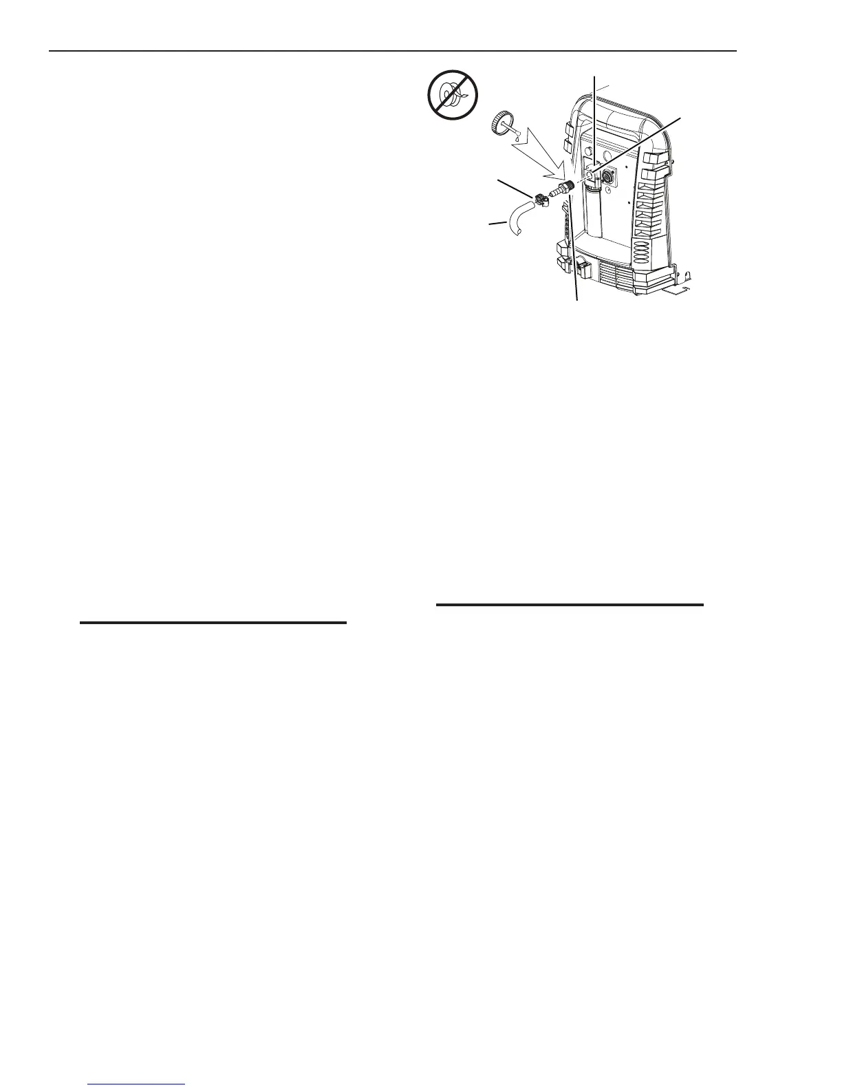
1. Connect the air line to the inlet port. The
illustration shows typical ttings as an
example.
NOTE
For a secure seal, apply thread sealant to the fitting
threads, according to manufacturer's instructions.
Do not use Teflon tape as a thread sealer, as small
particles of the tape may break off and block the
small air passages in the torch.
Art # A-08320
Inlet Port
Filter Assembly
Hose Clamp
Gas Supply
Hose
1/4 NPT or ISO-R
to 1/4” (6mm) Fitting
Air Connection to Inlet Port
Installing Optional Single - Stage Air Filter
An optional lter kit is recommended for im-
proved ltering with compressed air, to keep
moisture and debris out of the torch.
1. Attach the Single - Stage Filter Hose to the
Inlet Port.
2. Attach the Filter Assembly to the lter
hose.
3. Connect the air line to the Filter. The
illustration shows typical ttings as an
example.
NOTE
For a secure seal, apply thread sealant to the fit-
ting threads, according to the manufacturer's
instructions. Do Not use Teflon tape as a thread
sealer, as small particles of the tape may break
off and block the small air passages in the torch.
Connect as follows: