cutmaster a120
OPERATION 4T-36 Manual 0-4989
4T.09 Recommended Cutting Speeds for Machine and Automated Torches
With Shielded Tip
Mild Steel
40A
Air Plasma / Air Shield
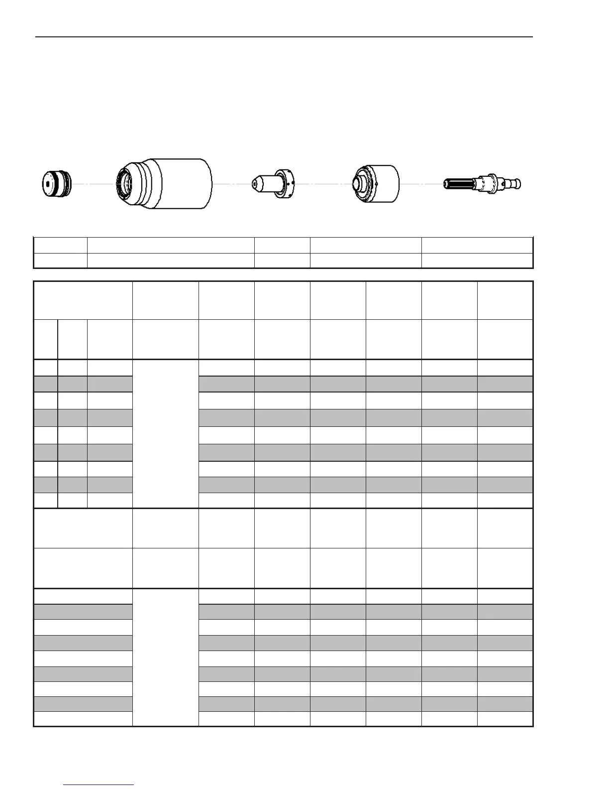
Shield Cap Maximum Life Shield Cup Tip Starter Cartridge Electrode
9-8245 9-8237 9-8208 9-8213 9-8215
Material
Thickness
Gas Pressure
(Air)
Arc Voltage
Torch
Working
Height
Travel Speed
Initial
Piercing
Height
Pierce Delay
Kerf Width
@ Rec.
Speed
(GA)
(in) inch
PSI
(torch lead
length)
Volts
(in)
(ipm) (in) (sec) (in)
20
0.036
75 (25')
80 (50')
107 0.16 130 0.16 0.0 0.06
16
0.060 113 0.16 120 0.16 0.0 0.06
14
0.075 108 0.16 90 0.16 0.1 0.06
12
0.105 111 0.16 75 0.16 0.2 0.06
10
0.135 114 0.16 65 0.16 0.3 0.07
3/16 0.188 115 0.16 65 0.16 0.4 0.07
1/4 0.250 118 0.16 45 0.16 0.5 0.07
3/8 0.375 123 0.16 23 0.16 1.2 0.08
1/2 0.500 128 0.16 18 0.16 2.0 0.08
Material
Thickness
Gas Pressure
(Air)
Arc Voltage
Torch
Working
Height
Travel Speed
Initial
Piercing
Height
Pierce Delay
Kerf Width
@ Rec.
Speed
(mm)
Bar
(torch lead
length)
Volts (mm) (mm/min) (mm) (sec) (mm)
1
5.2 (7.6)
5.5 (15.2)
108
4.1
3266
4.1
0.0 1.4
2
108 4.1 2239 4.1 0.0 1.5
3
112 4.1 1794 4.1 0.1 1.7
4
114 4.1 1651 4.1 0.2 1.7
5
115 4.1 1578 4.1 0.3 1.7
6
117 4.1 1256 4.1 0.4 1.7
8
121 4.1 853 4.1 0.5 1.7
10
124 4.1 565 4.1 1.2 1.8
12
127 4.1 485 4.1 2.0 1.9
BOLD TYPE indicates maximum piercing parameters.
 Loading...


