cutmaster a120
Manual 0-4989 4T-53 OPERATION
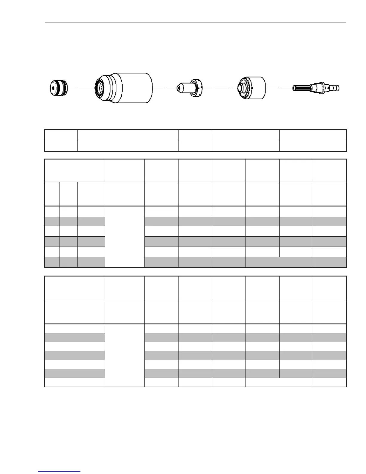
Stainless Steel
100A
Air Plasma / Air Shield
Shield Cap Maximum Life Shield Cup Tip Starter Cartridge Electrode
9-8239 9-8237 9-8212
9-8213
9-8215
Material
Thickness
Gas Pressure
(Air)
Arc Voltage
Torch
Working
Height
Travel Speed
Initial
Piercing
Height
Pierce Delay
Kerf Width
@ Rec.
Speed
(GA)
(in) inch
PSI
(torch lead
length)
Volts
(in)
(ipm) (in) (sec) (in)
1/4 0.250
75 (25')
75 (50')
114 0.16 110 0.18 0.00 0.08
3/8 0.375
116 0.16 70 0.18 0.10 0.09
1/2 0.500
119 0.16 45 0.18 0.30 0.10
5/8 0.625
130 0.19 20 0.23 2.00 0.11
3/4 0.750
135 0.19 15 0.23 2.80 0.11
1 1.000
140 0.19 10 Edge Start 0.11
Material
Thickness
Gas Pressure
(Air)
Arc Voltage
Torch
Working
Height
Travel Speed
Initial
Piercing
Height
Pierce Delay
Kerf Width
@ Rec.
Speed
(mm)
Bar
(torch lead
length)
Volts (mm) (mm/min) (mm) (sec) (mm)
6
5.2 (7.6m)
5.2 (15.2m)
114
4.1
2900
4.6 0.00
2.0
8 115
4.1
2265
4.6
0.10 2.2
10 116
4.1
1685
4.6
0.20 2.4
12 118
4.1
1285
4.6
0.30 2.4
15 127
4.6
685
5.7
2.00 2.7
20 136 4.8 360 5.7 2.80 2.8
25 140 4.8 260 Edge Start 2.8
BOLD TYPE indicates maximum piercing parameters. BOLD ITALIC indicates edge starts only.