cutmaster a120
Manual 0-4989 4T-55 OPERATION
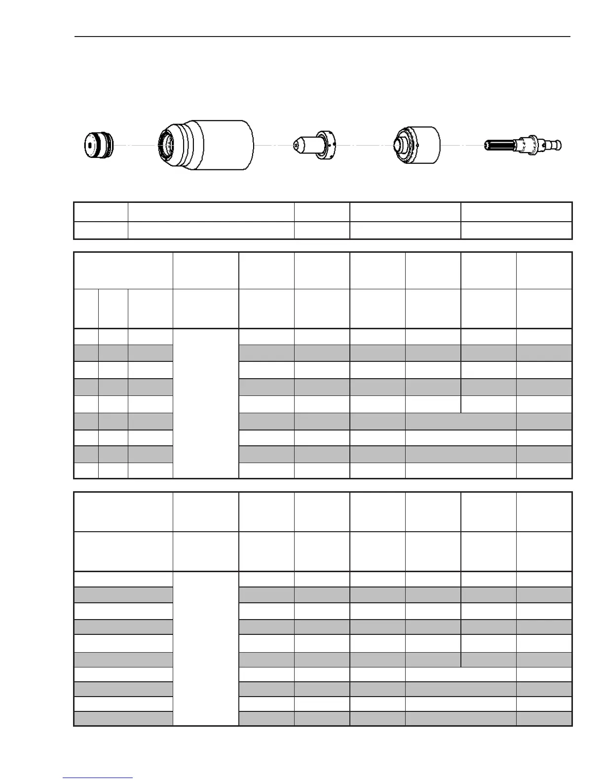
Mild Steel
120A
Air Plasma / Air Shield
Shield Cap Maximum Life Shield Cup Tip Starter Cartridge Electrode
9-8256 9-8237 9-8253
9-8213
9-8215
Material
Thickness
Gas Pressure
(Air)
Arc Voltage
Torch
Working
Height
Travel Speed
Initial
Piercing
Height
Pierce Delay
Kerf Width
@ Rec.
Speed
(GA)
(in) inch
PSI
(torch lead
length)
Volts
(in)
(ipm) (in) (sec) (in)
1/4 0.250
80 (25')
80 (50')
139 0.125 160 0.20 0.20 0.11
3/8 0.375 140 0.125 85 0.20 0.20 0.11
1/2
0.500 142 0.125 75 0.20 0.50 0.10
5/8 0.625 144 0.125 45 0.20 0.70 0.11
3/4 0.750 150 0.125 30 0.25 1.50 0.12
7/8 0.875 158 0.175 25 Edge Start 0.13
1 1.000 160 0.175 22 Edge Start 0.14
1-1/4 1.250 165 0.175 15 Edge Start 0.17
1-1/2 1.500 171 0.175 8 Edge Start 0.15
Material
Thickness
Gas Pressure
(Air)
Arc Voltage
Torch
Working
Height
Travel Speed
Initial
Piercing
Height
Pierce Delay
Kerf Width
@ Rec.
Speed
(mm)
Bar
(torch lead
length)
Volts (mm) (mm/min) (mm) (sec) (mm)
6
5.5 (7.6m)
5.5 (15.2m)
139
4.8
4270
5.08 0.20
2.8
8 140
4.8
3070
5.1
0.2 2.8
10 140
6.4
2120
5.08
0.30 2.8
12 142
6.4
1960
5.08
0.50 2.8
15 143
4.8
1355
5.08
0.70 2.8
20 152 4.8 725 6.4 1.6 3.1
25 160 4.8 570 Edge Start 3.6
30 164 4.8 430 Edge Start 4.0
35 168 4.8 290 Edge Start 4.3
40 173 4.45 150 Edge Start 4.4
BOLD TYPE indicates maximum piercing parameters. BOLD ITALIC indicates edge starts only.