Manual 0-2724 3-5 INSTALLATION PROCEDURES
5. Refer to the following when using high pressure
gas cylinders as the gas supply:
CAUTION
Pressure should be set at 100 psi (6.9 bar) at the
high pressure gas cylinder regulator.
Do not use an air line filter with high pressure gas
cylinders.
a. Refer to the manufacturer’s specifications for
installation and maintenance procedures for
high pressure gas regulators.
b. Examine the cylinder valves to be sure they
are clean and free of oil, grease or any foreign
material. Momentarily open each cylinder
valve to blow out any dust which may be
present.
c. The cylinder must be equipped with an ad-
justable high-pressure regulator capable of
outlet pressures up to 100 psi (6.9 bar) maxi-
mum and flows of up to 300 scfh (141.5 lpm).
6. Slide the gas supply hose over the barb fitting in-
stalled in Step 2. Supply hose must be at least #4
hose (1/4 in or 6 mm I.D.).
7. Secure the gas supply hose in place with the ad-
justable hose clamp.
3.09 Connecting Torch Leads
CAUTION
This system is designed for use with the PCH/M-
102 torch only. Do not connect any other torch to
this power supply.
The instructions for connecting the Torch Leads to the
Power Supply are different depending on the type of
leads. This sub-section covers connecting the Torch for
the following applications:
A. Hand Systems
B. Machine Systems (Unshielded Leads)
C. Machine Systems (Shielded Leads)
The Torch Leads must be properly installed to the Power
Supply for proper operation. If the torch leads were not
factory-installed, make all torch connections to the Torch
Bulkhead Panel for the desired application.
Equipment ordered as a system will have the Torch fac-
tory connected to the Power Supply.
A. Hand Systems
WARNING
Disconnect primary power at the source before as-
sembling or disassembling the power supply, torch
parts, or torch and leads assemblies.
1. Remove the Cover of the power supply for access
to the torch bulkhead panel.
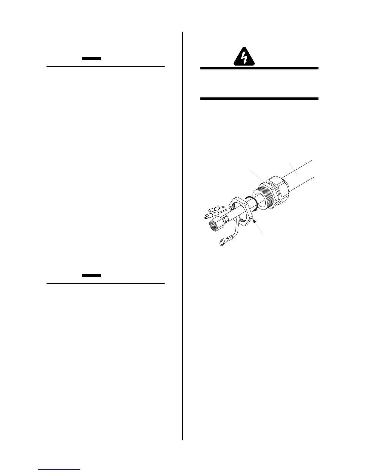
2. Remove the retaining nut from the strain relief
supplied on the end of the Torch Leads.
Retaining Nut
Strain Relief
Torch Leads
Assembly
A-02836
Figure 3-6 Torch Strain Relief RetainingNut
3. Feed the torch lead ends and the Strain Relief into
the hole in the unit.
4. Secure the Strain Relief with the retaining nut re-
moved earlier.
5. Connect the torch Negative/Plasma Lead to the
bulkhead connection inside the Power Supply.

 Loading...


