Manual 0-2745 17 SECTION 4: SERVICE TROUBLESHOOTING
a. Wait for fans to cool unit and refer to Operating
Manual 0-2744, Section 2.03, for proper Duty
Cycle
3. Faulty Fan or Logic/Gate PC Board
Measure for 115 VAC on the Logic/Gate PC Board
from J2-2 to J2-8 and J2-3 to J2-9.
• If voltage is correct, replace Fan Assembly
• If voltage is incorrect, replace Logic/Gate PC
Board
4. Faulty temperature circuit
a. Check temperature circuit per Section 4.09-F;
repair as necessary
E. AC indicator ON; TEMP indicator OFF; No gas
flow; GAS and DC indicators OFF
1. RUN/SET/LATCH switch in RUN(or LATCH) posi-
tion
a. Switch to SET position
2. Gas supply not connected to unit
a. Connect to gas supply.
3. Gas supply not turned on
a. Turn gas supply on.
4. Gas supply inlet presure too high
a. Set gas supply inlet pressure between 100-110
PSI.
5. Faulty RUN/SET/LATCH switch
a. Check continuity.
6. Faulty gas solenoid circuit
a. Test gas solenoid circuit per Section 4.09-G; re-
pair as necessary.
F. AC indicator ON; GAS indicator OFF; Gas flows;
DC indicator OFF
1. Gas pressure too low
a. See torch manual for operating pressures
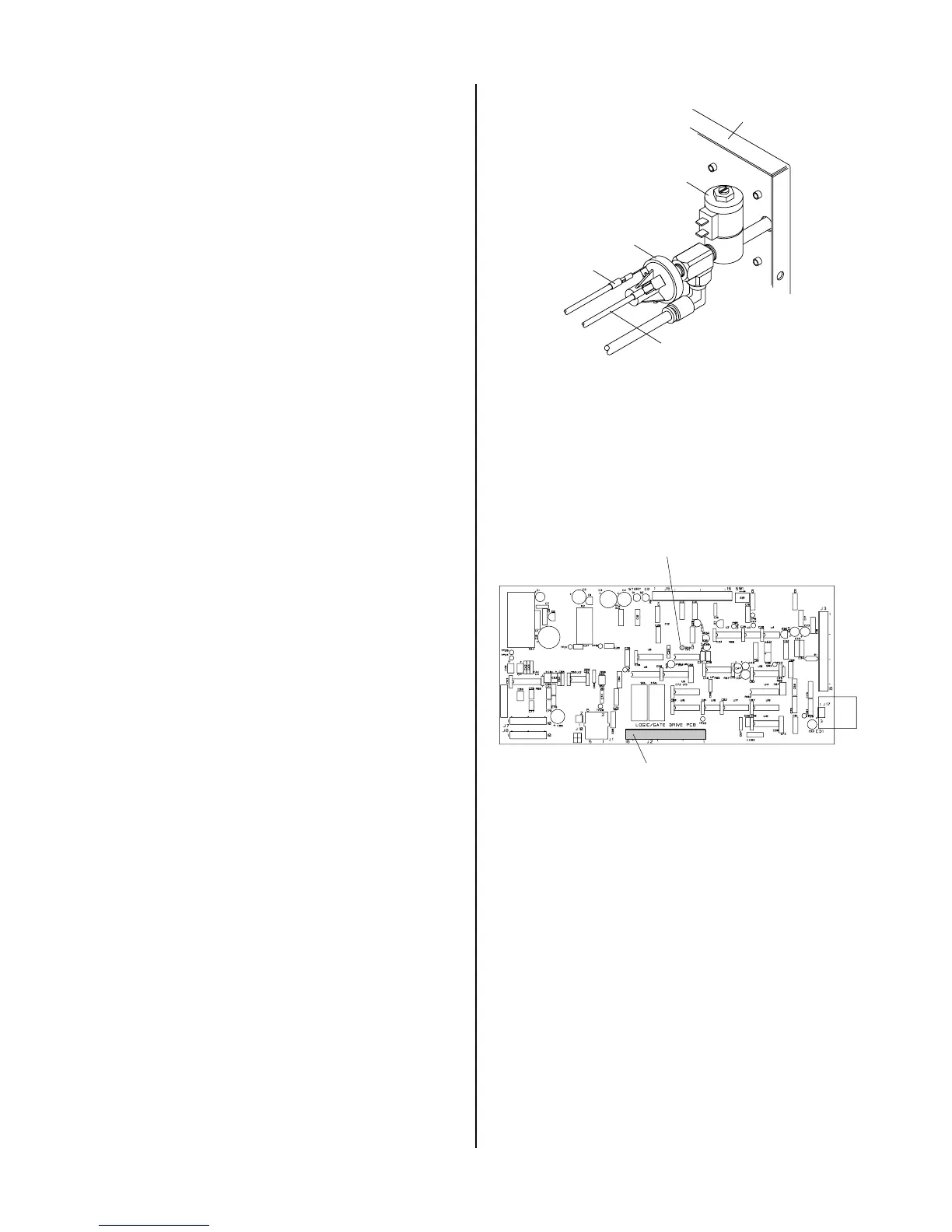
2. Faulty pressure switch
Measure for DC voltage from wire #51 to wire #50
at the gas pressure switch at the rear of the Rear
Panel Assembly.
a. If 12vdc and pressure is above 50 PSI, replace
gas pressure switch.
Wire #51
Wire #50
Gas Pressure Switch
Rear Panel
Gas Solenoid
A-01184
5. Faulty Wiring or Logic/Gate PC Board
Check for DC voltage from Logic/Gate PC Board
J2-13 to TP1 (GND)
• If less than a volt, replace Logic/Gate PC Board
If 12 VDC check wiring to PS1.
A-02546
J2
TP1 (GND)
Logic/Gate PC Board
G. AC indicator ON; Gas flows; GAS and DC
indicators ON; Arc in torch without pressing
torch switch
1. Faulty torch switch
a. Refer to appropriate Torch Instruction Manual
and check continuity
2. Faulty torch leads
a. Refer to appropriate Torch Instruction Manual
and check continuity
3. Faulty Pilot Output PC Board
Remove power from the power supply. Discon-
nect J12 and J13 from the Pilot PC Board.
Check for an open between J12 pin 1 to J12 pin 3
on the Pilot Output PC Board.