Manual 0-2745 61 APPENDIX
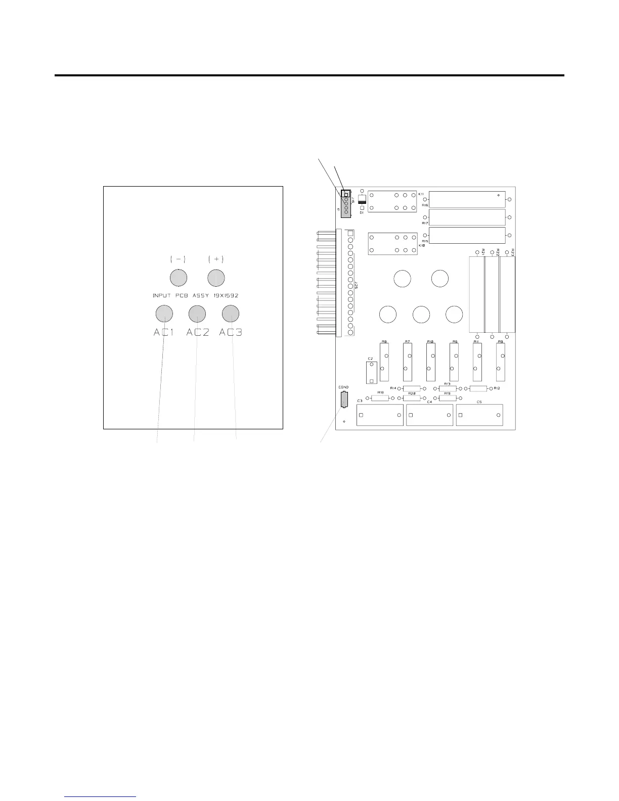
APPENDIX VII: INPUT PC BOARD LAYOUT
Input PC Board Signals
J16-1 Logic low inrush signal from Logic PCB J10-1
J16-2 Unregulated +18VDC to inrush Relay K11
J16-3 Not used
J16-4 Not used
J16-5 Not used
CGND Chassis Ground to Chassis Ground
(+) (+) Output to the Cap Board (+) E25
(-) Rectifier (-) Module (-) Output to the Cap Board (-) E26
AC1 AC Input Phase 1 from the contactor T1 and T4
AC2 AC Input Phase 2 from the contactor T2
AC3 AC Input Phase 3 from the contactor T3
Input PC Board
A-02551
Solder Side of PC Board Component Side of PC Board
AC1
AC2
AC3
CGND
J16
2-position connector