SECTION 4: SERVICE TROUBLESHOOTING 20 Manual 0-2745
2. Faulty Logic Gate
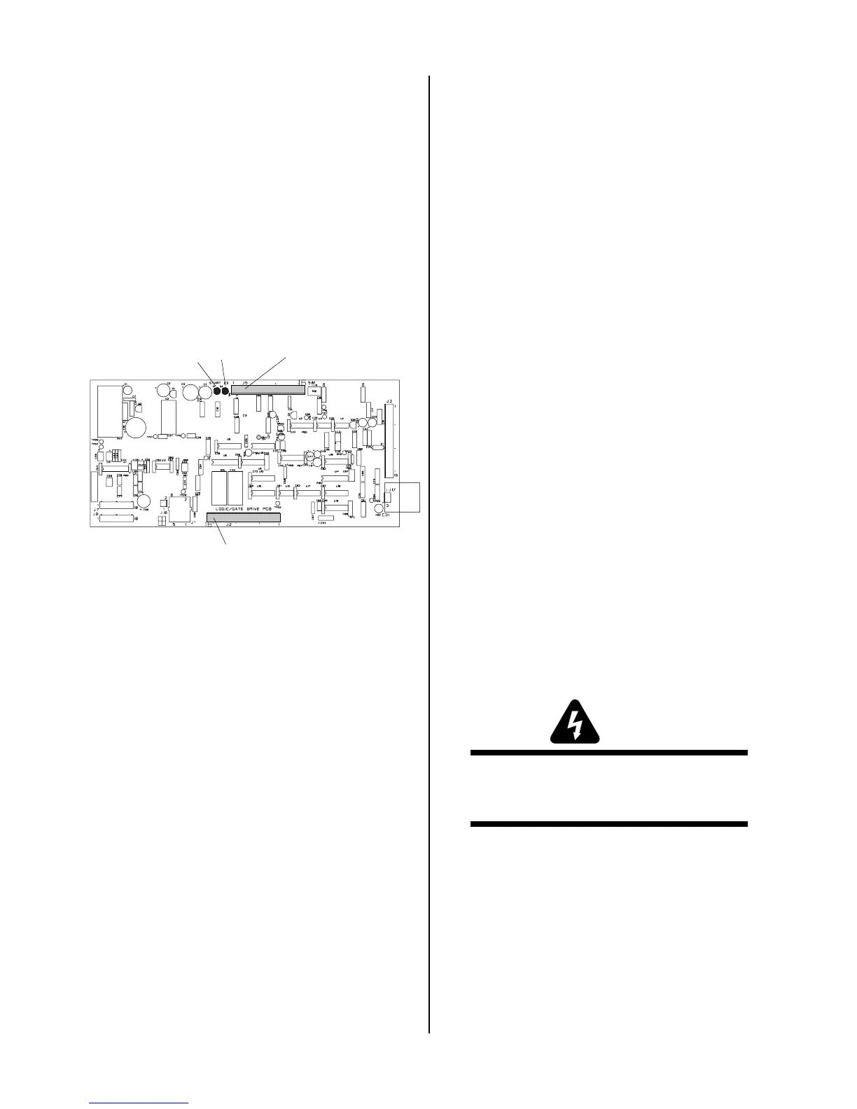
Check the following indicators inside the power
supply:
• Pilot Indicator (D39) on the Logic/Gate PC Board
is ON during the pilot then OFF during the
main arc transfer
• CSR indicator (D20) on the Logic/Gate PC Board
is OFF during the pilot then ON during the
main arc transfer
While trying to transfer, measure voltage. If D20
on the Logic/Gate PC Board does not turn on,
replace Logic/Gate PCB.
A-02548
J2
Logic/Gate PC Board
J5
D2
D1
B. When operating at amperages over 35 amps, the
amperage drops off after the main cutting arc
initiates.
Check the following indicator inside the Power Sup-
ply:
• Drag indicator (D36) on the Logic/Gate PC
Board is ON when the torch tip comes in con-
tact with the workpiece.
1. Cutting tip in contact with the workpiece.
a. Maintain standoff distance 1/8"-3/8" between
cutting tip and workpiece. (See SW-1 Drag Dis-
able)
2. Faulty PCR Relay
a. With power off, measure for continuity between
wires #12 and #14. If continuity is found, re-
place PCR.
3. Faulty Logic/Gate PC Board
If torch tip is off the workpiece and the drag indi-
cator, D36, on the Logic/Gate PC Board is still ON,
then replace the Logic/Gate PC Board.
4.09 Test Procedures
The test procedures in this subsection are referenced in
the troubleshooting section.
A. Safety Precautions
1. Significant DC Voltage exists after removal of input
power. Allow 2 minutes for discharge time. Voltage
measured on input capacitors must be zero before
performing service on the power supply.
2. Do Not touch electrical components with any part of
the human body when power is applied.
3. Keep away from any moving parts.
4. Hot surfaces can cause severe burns. Allow equip-
ment to cool before servicing.
5. Electrostatic discharge can damage printed circuit
board assemblies. Transport printed circuit boards in
proper anti-static shielded packages. Use proper
grounding techniques with wrist strap before handling
printed circuit boards.
6. Misaligned plugs can cause printed circuit board dam-
age. Be sure plugs are properly aligned and com-
pletely seated.
7. Excessive pressure can damage printed circuit board.
Use only minimal pressure and gentle movement
when disconnecting or connecting printed circuit
board plugs.
B. Opening Power Supply Enclosure
The left side panel of the Power Supply must be removed
to gain access to the input power connections and the
input voltage selection.
WARNING
Disconnect primary power at the source before as-
sembling or disassembling the Power Supply, torch
parts, or torch and leads assemblies.
1. Using a phillips head screw driver remove the five
screws which secure the left side panel (viewed from
front of unit) to the frame assembly.