SECTION 4: SERVICE TROUBLESHOOTING 18 Manual 0-2745
a. Replace Pilot Output PC Board if reading is not
open.
A-01399
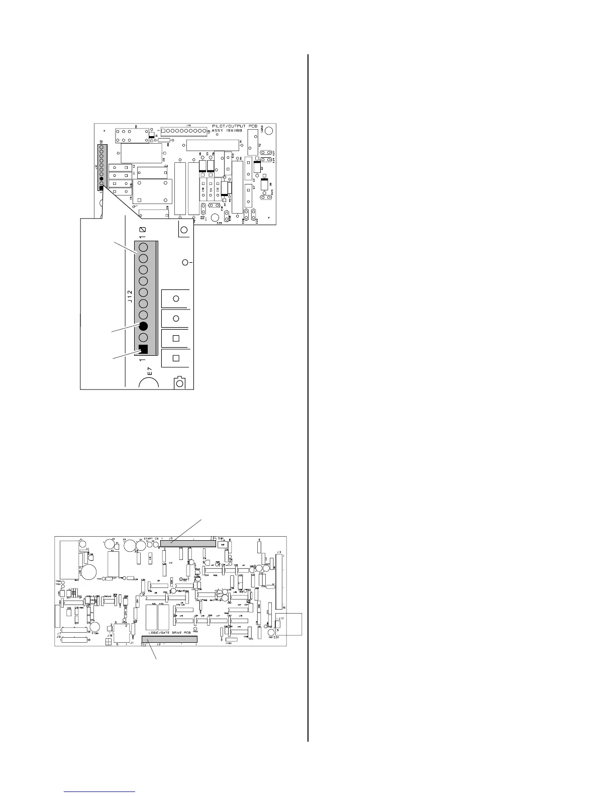
Pin 3
J12
Pin 1
Pilot Output PC Board
Top
4. Faulty Logic/Gate or Pilot PC Board
Check for DC voltage from Logic/Gate PC Board
J5 pin 8 to J5 pin 9.
a. Replace Logic/Gate PC Board if voltage is
12VDC.
A-02547
J2
Logic/Gate PC Board
J5
4.07 Pilot Arc Problems
Locate your symptom below:
A. AC indicator ON; TEMP indicator off; No gas
flow; GAS and DC indicators OFF (Torch Switch
must be pressed)
1. Faulty hand torch parts or Logic/Gate PC Board
Check start indicator, D1, on the Logic/Gate PC
Board.
a. If start indicator D1 is ON, replace Logic/Gate
PCB.
b. If start indicator D1 on Logic/Gate PC Board is
OFF check the following:
Check Pilot/Output PC Board for 12 VDC between
J12 pin 1 to pin 3 with torch switch pressed.
• If voltage is correct, check Torch Switch and PIP
as needed per appropriate torch manual.
• If voltage is incorrect, replace Logic/Gate PC
Board
2. Faulty Logic/Gate PC Board
Measure for 12VDC on Logic/Gate PC Board be-
tween J5-8 and J5-9.
If voltage is less than 2VDC, replace Logic/Gate
PC Board.
B. AC indicator ON; TEMP indicator off; Gas flows;
GAS indicator ON; DC indicator blinks; Small arc
may be visible in torch
1. Faulty Pilot Output PC Board or Shorted Torch
a. Test per Section 4.09-H; repair as necessary
2. Faulty FET/Heatsink Assembly
a. Check per Section 4.09-I; repair as necessary
3. Faulty torch
a. Check torch per appropriate Torch Instruction
Manual
C. AC indicator ON; TEMP indicator off; Gas flows;
GAS and DC indicators ON; No arc in torch; No
arc at spark gap on CD PC Board; CD enable
indicator (D2) ON
1. Faulty CD PC Board
Measure for 36VAC betwen J11-1 and J11-3.
Measure DC voltage between J11-4 to J11-5 on CD
PC Board.