Manual 0-2745 21 SECTION 4: SERVICE TROUBLESHOOTING
Screws
(5 Places)
Left Side
Panel
A-01326
Ground Wire
2. Carefully pull the left side panel from the Power Sup-
ply a short distance (see note).
NOTE
There is a ground wire attached to the side panel.
3. Remove the nut securing the ground wire to the side
panel.
4. Close the enclosure by reversing the above steps.
C. Diode Testing Basics
Testing of diode modules requires a digital volt/ohmme-
ter that has a diode test scale. Remember that even if the
diode module checks good, it may still be bad. If in doubt,
replace the diode module.
1. Locate the diode module to be tested.
2. Remove cables from mounting studs on diodes to iso-
late the module.
3. Set digital volt/ohmmeter to diode test scale.
4. Using the Figures for each test, check each diode in the
module. Each diode must be checked in forward bias
(plus to negative) and reverse bias (negative to plus)
direction.
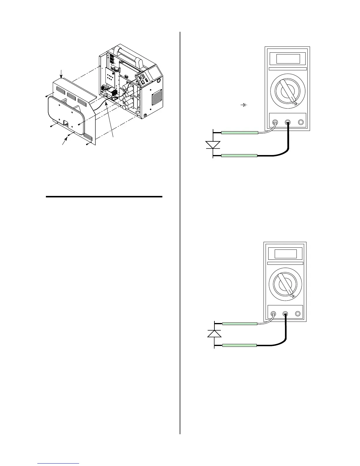
5. Connect the volt/ohmmeter positive lead to the an-
ode (+) of the diode and the negative lead to the cath-
ode (-) of the diode for forward bias testing (refer to
following figure). A properly functioning diode will
conduct in the forward bias direction and indicate be-
tween 0.3 to 0.9 volts.
0.75
VR
COM
A
A-00307
Anode
Cathode
Forward Bias
Diode Conducting
+
_
Diode Test Symbol
Testing Diode Forward Bias
6. Reverse the meter leads across the diode for reverse
bias testing (refer to following figure). A properly
functioning diode will block in the reverse bias direc-
tion and depending on the meter function will indi-
cate an open or “OL”.
OL
VR
COM
A
A-00306
Anode
Cathode
Reverse Bias
Diode Not Conducting
+
_
Testing Diode Reverse Bias
7. If a diode checks bad, replace the diode module.
8. Reconnect all cables to proper terminals.