SECTION 4: SERVICE TROUBLESHOOTING 22 Manual 0-2745
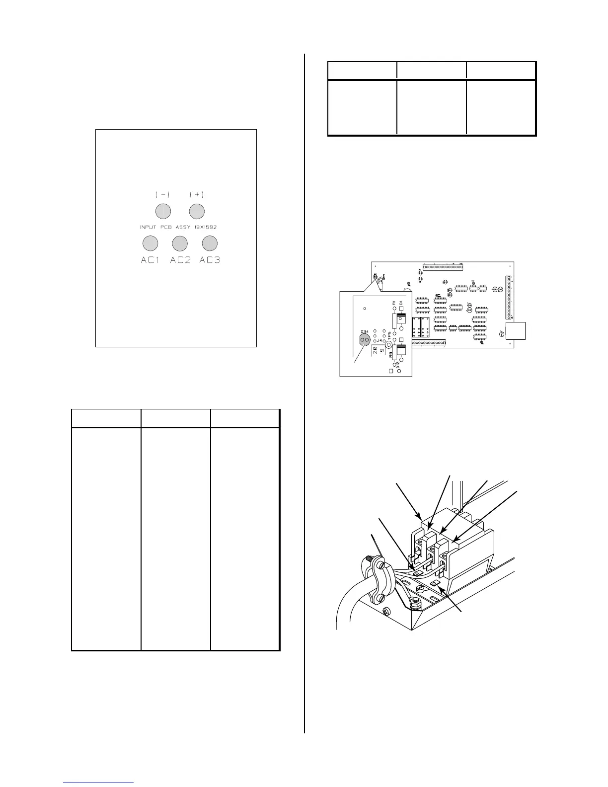
D. Input PC Board/Input Diode Test
Check Input PC Board for shorted input diode.
Input PC Board
Solder Side of PC Board
A-02563
Remove AC power and with an ohmmeter set on the di-
ode range make the following checks:
Meter (+) Meter (-) Indication
AC1 + Diode Drop
+AC1Open
AC2 + Diode Drop
+AC2Open
AC3 + Diode Drop
+AC3Open
AC1 (-) Open
(-) AC1 Diode Drop
AC2 (-) Open
(-) AC2 Diode Drop
AC3 (-) Open
(-) AC3 Diode Drop
The meter should indicate a diode drop in one direction
and an open in the other direction for each check.
If Input Bridge Diode is shorted, make the following
checks with an ohmmeter at the Main Contactor:
Meter (+) Meter (-) Indication
L1 T1 Open
L2 T2 Open
L3 T3 Open
If any test has resistance, then replace the Main Contac-
tor also.
E. Main Contactor (MC1) Test
Reconnect power and observe proper start-up procedure.
AC LED Indicator on the Front Panel should be ON. If
indicator is OFF there is no voltage to the Power Supply
or an overvoltage condition exists.
A-01395
D34
If indicator AC LED Indicator on Front Panel is OFF check
for proper AC input voltage per the following:
• Single Phase Units check at L1 and L2
• Three Phase Units check L1, L2, and L3
L1
L2
A-01379
L3
Main Contactor
(MC1)
Coil
Wire #59
Coil
Wire #55
Measure voltage on coil of contactor, approximately 117
VAC between wires #70 and #75.
• If voltage is correct, replace Main Contactor.
• If voltage is incorrect, replace Logic/Gate PC Board.