Manual 0-2745 23 SECTION 4: SERVICE TROUBLESHOOTING
F. Temperature Circuit Test
Test the temperature circuit per the following:
1. Place the front panel ON/OFF switch to the OFF
position.
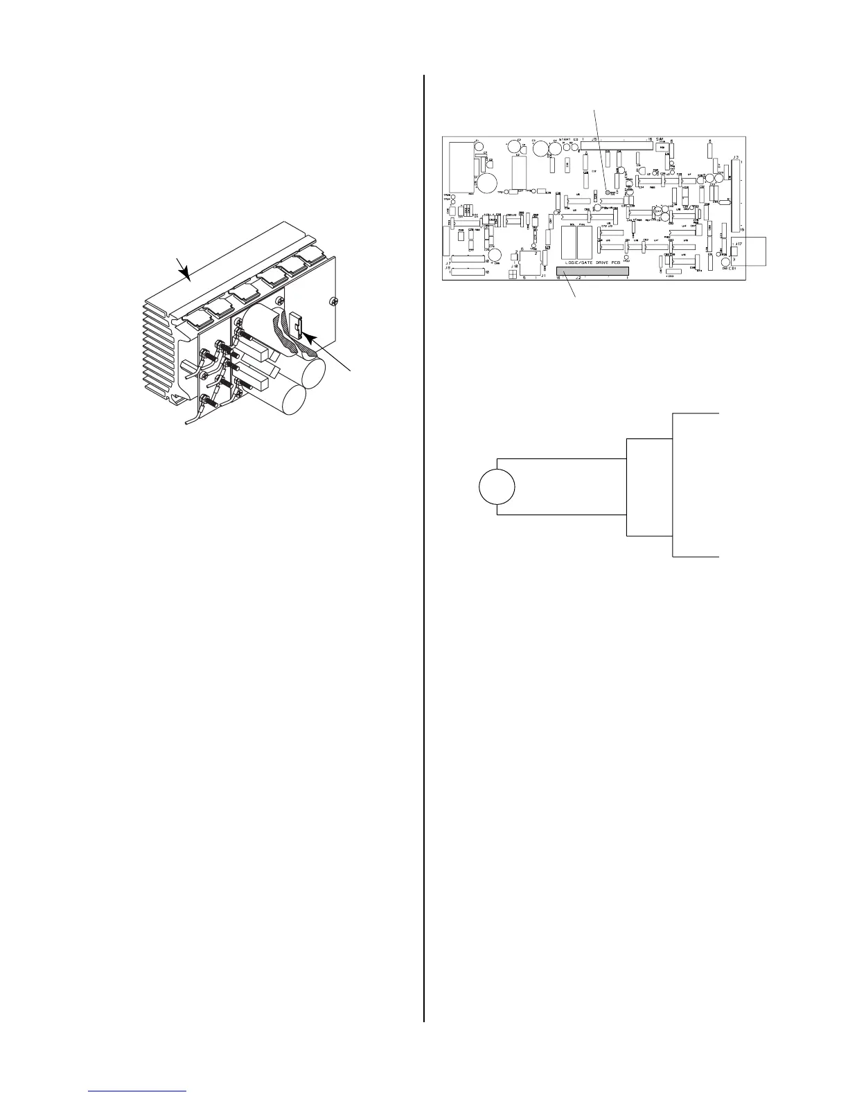
2. Disconnect ribbon cable from the Upper FET/
Heatsink Assembly at J6.
A-01421
J6
FET/Heatsink and
Capacitor PC Board
Assembly
3. Place the front panel ON/OFF switch to ON.
4. Check status of the TEMP indicator. If indicator
has gone OFF, then remove power and replace the
Upper FET/Heatsink Assembly.
5. Place the front panel ON/OFF switch to the OFF
position.
6. Disconnect ribbon cable from the Lower FET/
Heatsink Assembly at J6.
7. Place the front panel ON/OFF switch to ON.
8. Check status of the TEMP indicator. If indicator
has gone OFF, then remove power and replace the
Lower FET/Heatsink Assembly.
9. Place the front panel ON/OFF Switch to the OFF
position.
10. Remove power from unit.
11. Disconnect connector from J2.
12. Check for short on connector (harness end) be-
tween J2-15 & 16.
If shorted, Replace TS1.
If no short, replace Logic/Gate PC Board.
A-02546
J2
TP1 (GND)
Logic/Gate PC Board
G. Gas Solenoid Circuit Test
Make the following voltage checks per the circuit dia-
gram and replace the faulty part as required.
A-01198
Gas
Solenoid
Wire #56
Wire #52
J2
4
10
Logic PC
Board
1. Check for 115 VAC from Wire #56 to wire #52 at the
gas solenoid.
If approximately 115 VAC replace solenoid.
If no voltage is present proceed to Step 2.
2. Measure for 115 VAC from J2-4 to J2-10 at the Logic/
Gate PC Board.
If voltage is not correct replace Logic/Gate PC
Board.
H. Pilot Arc Circuit
1. Check across E23 to E24 at the Pilot Output PC
Board. There should be a diode drop across E23
to E24 in one direction and an open in the other.
If shorted, remove the wires at E23 and E24 at
the Pilot Output PC Board and check again.
Replace Pilot Output PC Board if shorted from E23
to E24 (with wires #17 and #16 removed).
Check for shorted torch Pilot Output PCB is not
shorted. Check for short between E8 and E22.