SECTION 4: SERVICE TROUBLESHOOTING 24 Manual 0-2745
If shorted, replace Pilot/Output PCB.
2. Measure between E9 to E8 and E24 on Pilot/Out-
put PC Board. If shorted, remove wires on E8 E9
and E24 and re-check PCB.
If shorted, replace Pilot/Output PCB.
If no longer measures shorted, check for short
in torch or leads.
I. FET/Heatsink Circuit Tests
The FET/Heatsink circuit tests require various checks to
isolate the possible fault to the FET/Heatsink Assembly.
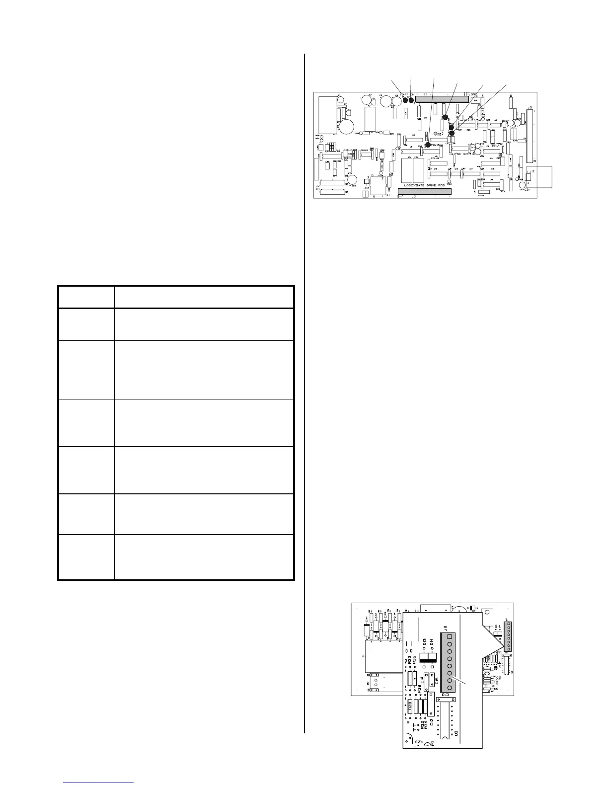
There are several internal indicators (LED's) on the Logic/
Gate PC Board to help in troubleshooting.
The indicators on the Logic/Gate PC Board as follows:
Indicator Meaning
D15
T orch S witch E nable - W hen ON
indicates torch switch is
D2
CD E nable - Initiates spark gap
on CD PC Board. Indicator
should come ON then go OF F
after a pilot arc has been
D20
CS R - Indicates main cutting arc
is establis hed.
D39
Pilot ON - Indicates that a pcr
Relay drive is active. OF F
during cutting.
D45
PW M E nable - indicates P W M
IC which provides Gate Drive
s ignal to F E T P CB is active.
D36
Drag On - When ON indicates
that the torch tip is making
contact with the workpiece.
A-02550
Logic/Gate PC Board
D1
D45
D39
D36
D20
D2
1. No DC Output
An open circuit voltage of approximately 280 to 325
VDC (depending on input power selected) is pro-
duced when switching transistors in the FET/
Heatsink Assemblies are turned ON by a PWM En-
able signal from the Logic/Gate PC Board. A circuit
on the Logic/Gate PC Board monitors the output volt-
age. When the output voltage drops below 60 VDC,
indicating a problem exists, the Logic/Gate PC Board
sends a signal which turns OFF the PWM Enable sig-
nal to the Logic/Gate Drive PC Board. Because this
happens in less than 50 milliseconds, it is not easy to
take voltage readings to find the source of the prob-
lem.
The Torch Switch Enable indicator, D1, turns ON when
the torch switch is pressed. At this point the gas be-
gins to flow. When the preflow time is over the PWM
Enable signal is given, PWM turns on, and the DC
indicator at the front panel turns ON. When the PCR
Drive/Pilot On Indicator, D39, turns ON.
If the PWM Enable indicator, D45, does not come ON
then replace the Logic/Gate PCB.
If the PWM Enable indicator, D45, turns ON then OFF
immediately, the following test should be performed:
a. Disconnect J11 from the CD PC Board to dis-
able the CD signal.
A-01202
J11
CD PC Board