Manual 0-2745 25 SECTION 4: SERVICE TROUBLESHOOTING
b. Connect a jumper between TP1 and TP8 on the
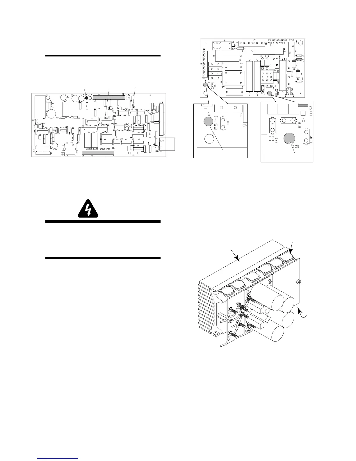
Logic/Gate PC Board in the unit.
NOTE
Before pressing the trigger, make sure no faults were
found on the Pilot Board and in the torch.
A-02552
Logic/Gate PC Board
TP8D1
TP1
This will cause the gas to flow continuously and the
DC indicator on the front panel to turn ON.
WARNING
Connector J11 on the CD PC Board must be dis-
connected to prevent electrical damage to measur-
ing equipment when testing the open circuit volt-
age (OCV)
c. Press and hold the hand torch switch (Logic/
Gate PC Board Start indicator, D1, turns ON).
After 2 seconds D45 turns on (Logic/Gate
PCB). If D45 does not turn on, replace Logic/
Gate PBB.
d. Measure open circuit voltage between E29 (+)
to E7 (-) at the Pilot Output PC Board.
e. If voltage is low, disconnect wire from E24 on
the Pilot Output Board and recheck steps c-d.
If voltage is okay, then check torch & leads. If
voltage is still low, disconnect wires 11-12 (from
FET PCB to Pilot Output PCB). If voltage ap-
proximately 325, check torch *& leads.
Make sure wires #11 & #12 which connect the
FET assemblies to each other remain con-
nected. Check for output voltage between E17
& E18. If voltage is OV-, replace both FET As-
semblies. if voltage is approximately 325 VDC,
replace Pilot/Output PC Board.
A-01401
Pilot Output PC Board
E29
E7
Top
2. MOSFET Resistance Checks
The Power Supply contains two identical FET/
Heatsink Assemblies. On each assembly there are two
MOSFET devices that must be checked. Use an ohm-
meter to check for the proper resistance of the
MOSFET's per the following procedure:
a. Locate Q1 and Q6 on the FET/Heatsink Assembly.
A-01422
Q1
FET/Heatsink and
Capacitor PC Board
Assembly
Q6
b. Place the meter (+) lead on gate lead of Q1 and
meter (-) lead on source lead of Q1. The meter
should indicate approximately 2.5K ohms.