SECTION 4: SERVICE TROUBLESHOOTING 26 Manual 0-2745
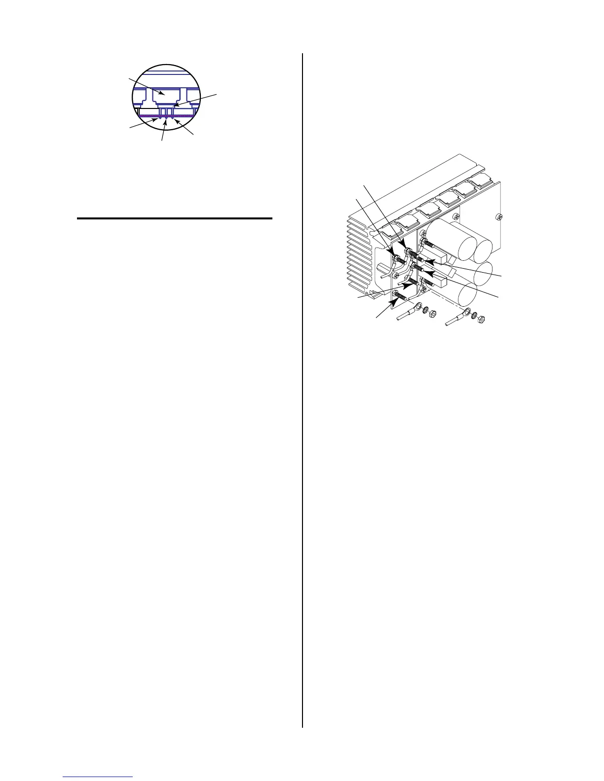
A-00553
MOSFET
Spring
Clip
Gate
Drain
Source
c. Place the meter (+) lead on drain lead of Q1 and
meter (-) lead on source lead of Q1. The meter
should indicate >100K ohms.
NOTES
Make measurements near the body of each
MOSFET.
Be sure that the meter lead probes penetrate the
protective coating on the MOSFET.
d. Place the meter (+) lead on drain lead of Q1 and
meter (-) lead to the heatsink. The meter should
indicate >1 meg ohms.
e. Place the meter (+) lead on gate lead of Q6 and
meter (-) lead on source lead of Q6. The meter
should indicate approximately 2.5K ohms.
f. Place the meter (+) lead on drain lead of Q6 and
meter (-) lead on source lead of Q6. The meter
should indicate >100K ohms.
3. FET Reset Diode Check
Use an ohmmeter set to the diode function and check
the reset diode per the following procedure:
a. Place the meter (+) lead on E14 and the meter (-)
lead on E1B of the FET/Heatsink Assembly Ca-
pacitor PC Board to check the reset diode. The
meter should indicate between 0.4 to 0.6 volts us-
ing the diode function.
b. Reverse the meter leads and the indication should
be a capacitor charging.
c. Place the meter (-) lead on E14 and the meter (+)
lead on E2B of the FET/Heatsink Assembly Ca-
pacitor PC Board to check the reset diode. The
meter should indicate between 0.4 to 0.6 volts us-
ing the diode function.
d. Reverse the meter leads and the indication should
be a capacitor charging.
If the indication is a short, then replace the FET/
Heatsink Assembly.
4. FET Output Rectifier Check
Use a digital meter, diode or ohms function, to check
the forward and reverse bias of the output rectifiers
on the FET/Heatsink Assemblies per the following
procedure:
a. Remove the wire from E16 and E18 on the Upper
and Lower FET/Heatsink Assemblies.
A-01423
E16
E18
E19
E17
E14
E15
b. Place the meter (+) lead on E16 and the meter (-)
lead on E18 of the FET/Heatsink Assembly to
check the output rectifier forward bias. The meter
should indicate between 0.3 to 0.6 volts using the
diode function or 100K ohms using the ohms func-
tion.
c. Place the meter (+) lead on E18 and the meter (-)
lead on E16 of the FET/Heatsink Assembly to
check the output rectifier reverse bias. The meter
should indicate 'OL' using the diode function or
100K ohms using the ohms function.
d. Place the meter (+) lead on E17 and the meter (-)
lead on E19 of the FET/Heatsink Assembly to
check the output rectifier forward bias. The meter
should indicate between 0.3 to 0.6 volts using the
diode function or 100K ohms using the ohms func-
tion.
e. Place the meter (+) lead on E19 and the meter (-)
lead on E17 of the FET/Heatsink Assembly to
check the output rectifier reverse bias. The meter
should indicate 'OL' using the diode function or
100K ohms using the ohms function.
f. Place the meter (+) lead on E18 and the meter (-)
lead on the heatsink of the FET/Heatsink Assem-
bly to check the output rectifier resistance to
ground. The meter should indicate >1 meg ohms.