SECTION 5: REPLACEMENT PROCEDURES 36 Manual 0-2745
4. Disconnect the lead wire on terminal E17 of the top
FET/Heatsink Assembly.
5. Remove the four mounting screws securing the Out-
put Inductor Assembly to the chassis.
6. Remove the Output Inductor Assembly from the
unit.
7. Install the replacement Output Inductor Assembly
by reversing the above procedure (see NOTE).
NOTE
The four screws securing the mounting plate to
the chassis should have a maximum of 2 to 5 threads
protruding through the left side of the chassis.
F. Auxiliary Transformer Assembly
Replacement
1. Remove the Left Side Panel per Section 5.04-B.
2. Remove the Right Side Panel per Section 5.04-C.
3. Disconnect the single pin connector on the white
wire coming from the Auxiliary Transformer As-
sembly.
4. On the voltage selection panel remove the pin 13
from connectors J19 (black wire), J20 (orange wire),
and J21 (brown wire) using a pin removal tool .
5. Disconnect the secondary wires by unplugging the
J15 connector from the Logic/Gate PC Board.
6. Remove the four mounting screws securing the
Auxiliary Transformer Assembly to the chassis.
7. Remove the Auxiliary Transformer Assembly from
the unit.
8. Install the replacement Auxiliary Transformer As-
sembly by reversing the above procedure noting
the following:
• Brown wire to pin 13 of the top connector (J21)
on the voltage selection panel.
• Orange wire to pin 13 of the middle connector
(J20) on the voltage selection panel.
• Black wire to pin 13 of the lower connector (J19)
on the voltage selection panel.
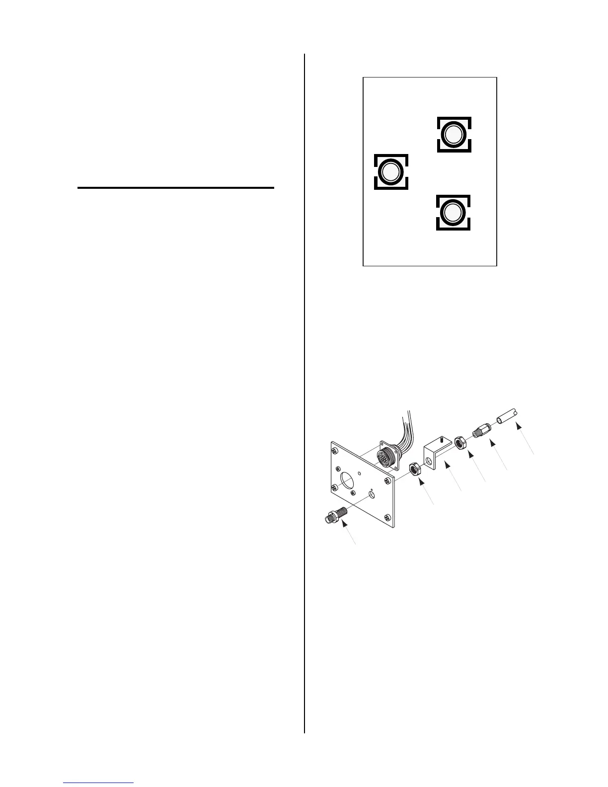
View of Voltage Selector Connectors
from the Left Side of
Center Chassis
460V
(brown wire)
220V
(black wire)
380-415V
(orange wire)
A-02561
G. Bulkhead Adapter Replacement
1. Remove the Right Side Panel per Section 5.04-C.
2. Remove Torch connection at the Bulkhead Adapter.
Nut
Fitting
Gas
Tube
Nut
Bulkhead
Adapter
Bracket
A-02562