Thermann Installer's Manual
Thermann X Split Heat Pump
10
INSTALLATION LOCATION
• The tank unit should be located as close as possible to the most frequently used hot water
outlet. The heat pump unit must be located outside and as close as practically possible to
the tank, but not further than 15 metres distance from it.
• Ensure sucient clearance around the heat pump unit to allow air to circulate and provide
adequate space for service maintenance of the unit (Figure 2). Note: Poor ventilation may
cause the unit to short cycle and this could increase power consumption by more than
10%.
• Do not install the heat pump unit in a confined space or where intake and exhaust airflow
is compromised.
• If the heat pump unit is installed facing a wall, exhaust air may stain the wall.
• There must be adequate space between the top of heat pump to allow for access to top
controls for servicing. Note: Avoid installing heat pump unit near bedroom windows.
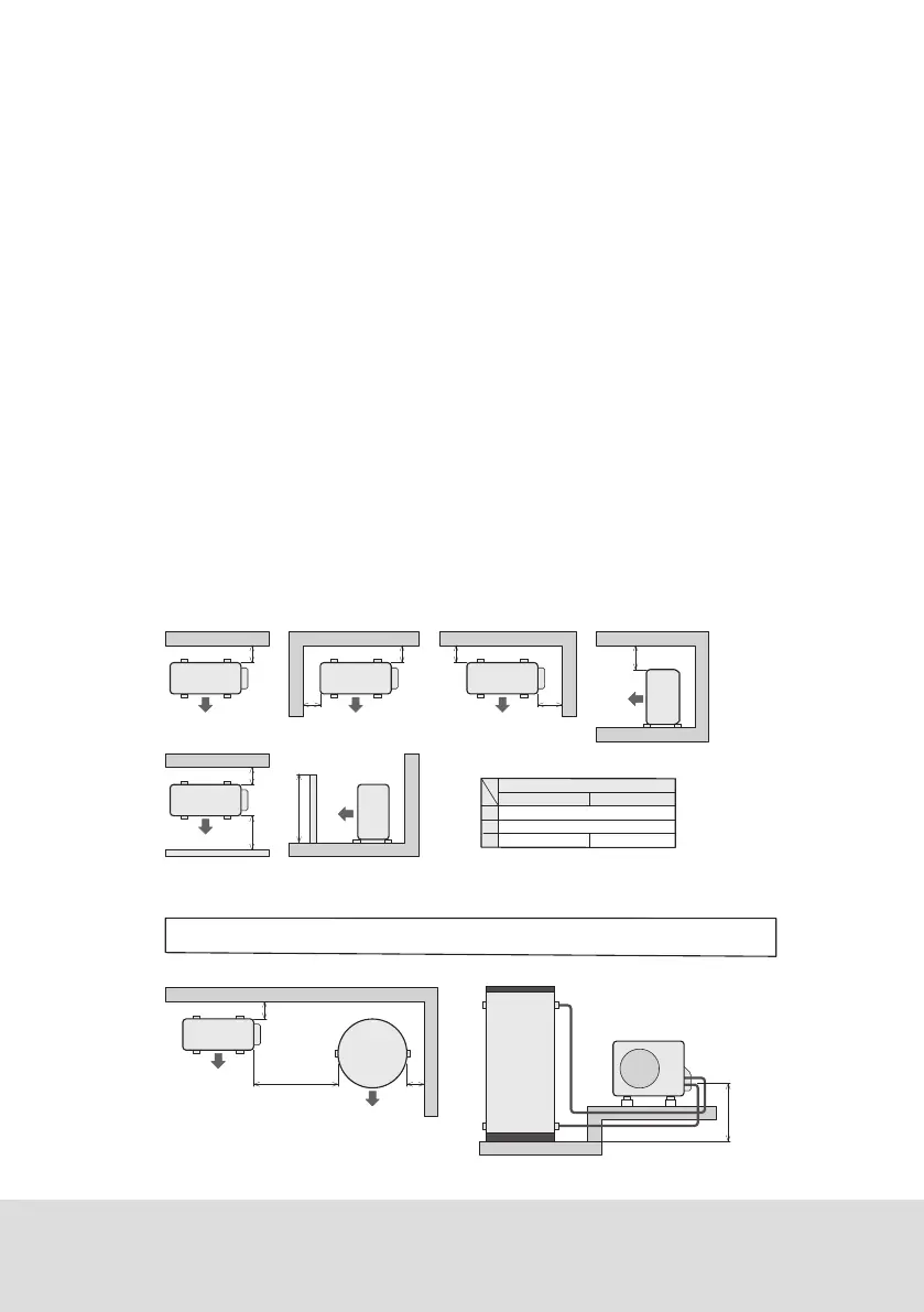
• The heat pump unit cannot be installed if there are obstacles such as walls in three or
more directions around the heat pump unit (see below figure).
Figure 2 : Restrictions on where the heat pump unit can be installed
A
A
A 150mm or more
H
B 300mm or more (service space)
C 600mm or more350mm or more
Over 1200mm
Within 1200mm
A
H
B
B
Heat Pump
Unit
Front
A
Heat Pump
Unit
Front
Front
Front
When there is no obstacle on the blowout side
[ Top view ]
A
C
Heat Pump
Unit
Front
Heat Pump
Unit
Front
Heat
Pump
Unit
When there is an obstacle on the blowout side
obstacle
Heat
Pump
Unit
heat pump unit
eht dna tinu knat eht neewteb ecaps eht htiw noitallatsni no snoitcirtseR : 3 erugi
150mm or more
A
50mm
or
more
Heat Pump
600mm or more
(maintenance space)
Unit
Heat Pump Unit
Top view standard layout Side view
Tank Unit
Total piping length : 15 metres maximum per way
Number of bends : 6 maximum
(A)Dierence in height between the base of tank and bottom of Heat pump should be no more than : 5 metres maximum.
Caution :
Keep the piping run to a minimum as the longer the pipe run the greater the potential for heat loss.
Tank Unit
Front
Front
Figure: Minimum Installation Clearances
Figure: Restrictions on installation with the space between the tank unit and the heat
pump unit