31
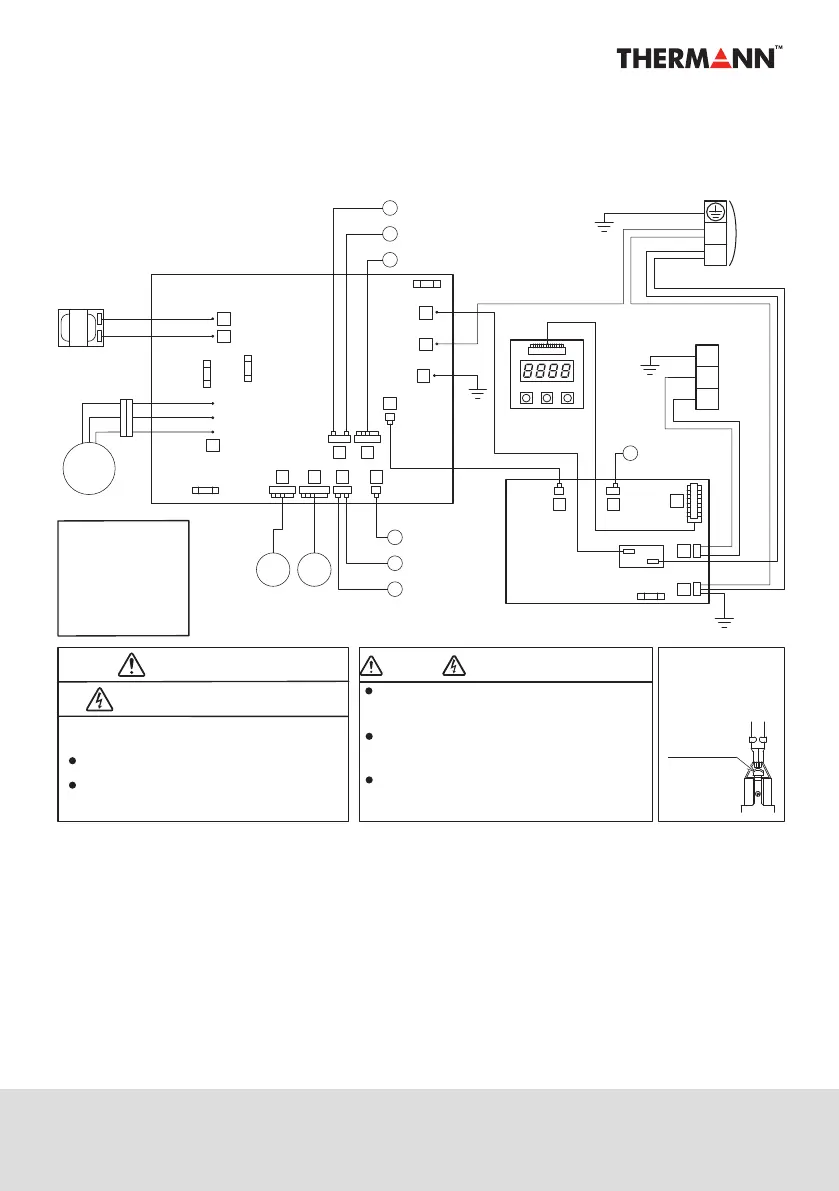
WIRING DIAGRAM
PCB
(CONTROL)
PCB
(OPERATION)
TERMINAL BLOCK
Warning when you fix electric components !
Electric Shock !
WARNING !
How to detach
locking terminal
Pull o while pressing
the locking lever.
Do not touch any part of the electric circuit
(including the wiring of thermistor and others),
as it has high voltage against the ground.
Pay attention not to damage the insulated wire
when you tighten the screw, as the exposed wire
may cause electric shock or malfunction.
Do not ground the oscilloscope when you operate.
You might destroy it. Also do not touch any metal
part of the oscilloscope while operating.
Caution Electric Shock
High Voltage
COLOR OF WIRE
B
BL
G
OR
Don't touch electrically charged parts, as electric
shock may occur even if they are switched o.
Be sure to wait at least 5 min. after turning o
the power.
: BLACK
: BLUE
R
W
Y
: GREEN
: ORANGE
: RED
: WHITE
: YELLOW
SENSOR
(TEMP., DEFROST)
SENSOR
(TEMP., OUTDOOR)
SENSOR
SENSOR
(TEMP., OUTGOING)
G/Y
(TEMP., RETURN)
G
G
G
BL
BL
BL
EXP. VALVE
SENSOR
(TEMP., SUCTION)
1
(TEMP., DISCHARGE)
2
4
15
11
23
9
8
5
2
1
6
12
13
8
U V
(
R
)
W
(
S
)
B
W
(
T
)
R
B
W
R
U
(
R
)
V
(
S
)
7
5
6
W
(
T
)
Y
OR
REACTOR
PCB
(MAIN)
B
B
B
BB
B
L
N
MOTOR
(FAN)
PUMP
FUSE CF1
FUSE CF5
(250V T3.15A)
FUSE CF1
(250V T3.15A)
FUSE CF3
FUSE CF4
POWER
Locking lever
TERMINAL BLOCK
TANK THERMISTOR
W
B
B
W
B
▲ ▼
Enter